Table of Contents
Advertisement
AIR CONDITIONER
AC160JNHFKH
AC180JNHFKH
AC200JNHFKH
AC180JNHPKH
AC200JNHPKH
AC160JXAFKH
AC160JXAFNH
AC200JXAFNH
AC180JXAFNH
AC200JXAPNH
AC180JXAPNH
SYSTEM AIR CONDITIONER
Indoor Unit
Model Name :
AC160JNHFKH
AC160JNHFKH
AC180JNHFKH
AC200JNHFKH
AC180JNHPKH
AC200JNHPKH
Model Code :
AC160JNHFKH/SA
AC160JXAFKH/SA
AC160JNHFKH/SA
AC160JXAFNH/SA
AC180JNHFKH/SA
AC180JXAFNH/SA
AC200JNHFKH/SA
AC200JXAFNH/SA
AC180JNHPKH/EU
AC180JXAPNH/EU
AC200JNHPKH/EU
AC200JXAPNH/EU
CONTENTS
1. Precautions
2. Product Speci cations
3. Disassembly and Reassembly
4. Troubleshooting
5. PCB Diagram
6. Wiring Diagram
7. Reference Sheet
Outdoor Unit
AC160JXAFKH
AC160JXAFNH
AC180JXAFNH
AC200JXAFNH
AC180JXAPNH
AC200JXAPNH
Advertisement
Table of Contents
Troubleshooting

Related Manuals for Samsung AC160JNHFKH


Summary of Contents for Samsung AC160JNHFKH
-
Page 1: Disassembly And Reassembly
SYSTEM AIR CONDITIONER Indoor Unit Outdoor Unit Model Name : AC160JNHFKH AC160JXAFKH AC160JNHFKH AC160JXAFNH AC180JNHFKH AC180JXAFNH AC200JNHFKH AC200JXAFNH AC180JNHPKH AC180JXAPNH AC200JNHPKH AC200JXAPNH Model Code : AC160JNHFKH/SA AC160JXAFKH/SA AC160JNHFKH/SA AC160JXAFNH/SA AC180JNHFKH/SA AC180JXAFNH/SA AC200JNHFKH/SA AC200JXAFNH/SA AC180JNHPKH/EU AC180JXAPNH/EU AC200JNHPKH/EU AC200JXAPNH/EU AIR CONDITIONER CONTENTS 1. -
Page 2: Table Of Contents
Contents 11. Precautions ............................1-1 Precautions for the Service ......................1-2 Precautions for the Static Electricity and PL ................1-3 Precautions for the Safety ....................... 1-4 Others ..............................12. Product Specifications ........................2-1 The Feature of Product ........................2-2 Product Specifications ........................ - Page 3 PCB Diagram and Parts list ......................5-1 INDOOR UNIT ........................5-1 5-2 OUTDOOR UNIT ........................ 5-4 Wiring Diagram ..........................6-1 Indoor Unit ................................6-2 Outdoor Unit ................................ Reference Sheet ..........................7-1 Refrigerating Cycle Diagram ......................7-2 Index for Model Name ........................Samsung Electronics...
-
Page 4: Precautions
- Release the valve caps on High and Low pressure side. - Use L wrench to close the valve on the high pressure side. - Approximately 2 minutes after, close the valve on the low pressure side. - Stop operation of the air conditioner. - Disconnect the pipes. Samsung Electronics... -
Page 5: Product Specifications
It can give the benefit to the installers and aries the reliability of the air conditioner. ■ Long Ambient Operation (In Low Temperature) It can arise the reliability and the capacity of the air conditioner, especially operated in low temperature. ■ Eco-friendly Product (Lead-Free, RoHS, WEEE) Samsung Electronics... -
Page 6: Product Specifications
(Cooling/Heating) In case of strongest air Outdoor unit 68/68 blow Refrigerant (R410A) 8000 (Charged for 30m) Liquid 9.52 Connecting Pipe 19.05 Additional Refrigerant (R410A) Standard Extension length(Total) Extension length(Elevation) Product Option 012474-1C50C0-20C8E1-320000 Option Code 020000-100000-200000-300000 Installation Option 030000-100000-200000-300000 Samsung Electronics... - Page 7 (Cooling/Heating) In case of strongest air Outdoor unit 63/65 blow Refrigerant (R410A) 4600 (Charged for 30m) Liquid 9.52 Connecting Pipe 19.05 Additional Refrigerant (R410A) Standard Extension length(Total) Extension length(Elevation) Product Option 01107C-1C50B0-27B414-370060 Option Code 020000-100000-200000-300000 Installation Option 030000-100000-2463E3-3B4402 Samsung Electronics...
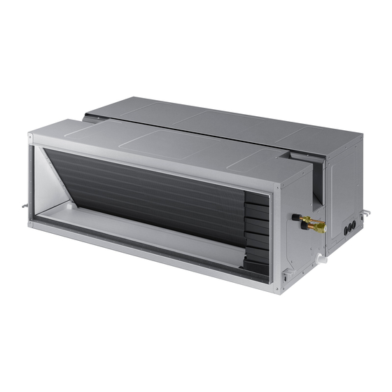
- Page 8 AC160JNHFKH ITEM AC160JXAFNH Indoor Unit Outdoor Unit IMAGE MWR-WE10N Remote Controller Power Product 3Φ, 380~415V/50Hz Indoor W*D*H 1350 x 910 x 450 Outdoor W*D*H 940 x 330 x 1420 Indoor Product kg(Net) 78.5 Outdoor Product kg(Net) Capacity Cooling/Heating(ISO) 16000/18000 Power input...
- Page 9 AC160JNHFKH ITEM AC160JXAFKH Indoor Unit Outdoor Unit IMAGE MWR-WE10N Remote Controller Power Product 1Φ, 220~240V/50Hz Indoor W*D*H 1350 x 910 x 450 Outdoor W*D*H 940 x 330 x 1420 Indoor Product kg(Net) 78.5 Outdoor Product kg(Net) Capacity Cooling/Heating(ISO) 16000/18000 Power input...
- Page 10 (Cooling/Heating) In case of strongest air Outdoor unit 63/65 blow Refrigerant (R410A) 4600 (Charged for 30m) Liquid 9.52 Connecting Pipe 19.05 Additional Refrigerant (R410A) Standard Extension length(Total) Extension length(Elevation) Product Option 01107C-1C50B0-27B414-370060 Option Code 020000-100000-200000-300000 Installation Option 030000-100000-2463E3-3B4402 Samsung Electronics...
- Page 11 In case of strongest air Outdoor unit 68/68 blow Refrigerant (R410A) 8000 (Charged for 30m) Liquid 9.52 Connecting Pipe 19.05 Additional Refrigerant (R410A) Standard Extension length(Total) Extension length(Elevation) Product Option 012474-1C50C0-20C8DC-320000 020000-100000-200000-300000 Option Code Installation Option 030000-100000-200000-300000 050000-100000-200000-300000 Samsung Electronics...
-
Page 12: Accessory
Indoor Unit INSU HOSE D DB62-11028E INSU TUBE OUT DB62-11028F ASSY DRAIN HOSE JOINT DB67-01191A Ass'y Drain Hose Joint DB90-06701A GROMMET-HANGER DB63-00237A RUBBER LEG DB73-20134A DB68-04921A INSTALLATION MANUAL (DVMS) Outdoor unit DB68-04924A INSTALLATION MANUAL (UB3) DRAIN PLUG DB67-00477A Samsung Electronics... -
Page 13: Disassembly And Reassembly
3. Disassembly and Reassembly ■ Necessary Tools Item Remark +SCREW DRIVER MONKEY SPANNER Samsung Electronics... -
Page 14: Indoor Unit
3-1 Indoor Unit ■ AC160JNHFKH/AC180JNHFKH/AC200JNHFKH/AC180JNHPKH/AC200JNHPKH Parts Procedure Remark Commom 1)Disasseble the Cover Control. - Unscrew 2 screws Samsung Electronics... - Page 15 Motor & Fan 1) Disassemble the connection wire to take the motor fan out 2) Disassemble th Cabinet Top Fan. - Unscrew 6 screws 3) Disassemble the Link Screw - Unscrew 3 screws 4) Disassemble Cabinet Top Fan. Samsung Electronics...
- Page 16 Parts Procedure Remark 5) Disassemble 2 Case Blower Top. - Unscrew 8 screws 6) Disassemble 1 Holder Motor. - Unscrew 2 screws 7)Disassemble Motor wire from 2 holder wire Samsung Electronics...
- Page 17 Parts Procedure Remark 8) After disassemble the Motor and Blower for the set, disassemble the Blower by use of 3mm wrench. 9)Disassemble 2 Case blower bottom. - Unscrew 4 screws 10)Disassemble the Bracket Motor. - Unscrew 4 screws Samsung Electronics...
- Page 18 Parts Procedure Remark Control Box 1)Disassemble Evap Sensor wire and EEV wire(20kW only) 2) Disassemble the Case Control. - Unscrew 3 screws Samsung Electronics...
- Page 19 Parts Procedure Remark Evap 1)Disassemble The Case Evap Top - [AC***JNHFKH]Unscrew 8 screws - [AC***JNHPKH]Unscrew 6 screws 2)Disassemble The Cushion Front. 3)Disassemble The Cushion Support. - Unscrew 1 screw Samsung Electronics...
- Page 20 Parts Procedure Remark 4)Disassemble The Cover pipe. - Unscrew 3 screws 5)Remove The cable tie on the Support Evap 6)Disassemble The Evap. - Unscrew 4 screws Samsung Electronics...
- Page 21 - Unscrew 3 screws 4)Disassemble 2 Case blower bottom. - Unscrew 4 screws 5)Disassemble Bracket Motor and Motor. - Unscrew 4 screws 6)After disassemble the Motor and Blower for the set, disassemble the Blower by use of 3mm wrench. Samsung Electronics...
- Page 22 Parts Procedure Remark 7)Disassemble The Case Blower Top. - Unscrew 8 screws 3-10 Samsung Electronics...
- Page 23 Parts Procedure Remark Control Box 1)Disassemble Evap Sensor wire and EEV wire(20kW only) 2) Disassemble the Case Control. - Unscrew 3 screws Samsung Electronics 3-11...
- Page 24 1)Disassemble The Case Evap Bottom - [AC***JNHFKH]Unscrew 11 screws - [AC***JNHPKH]Unscrew 7 screws 2)Disassemble The Drain Pan 3)Disassemble The Cover pipe. - Unscrew 3 screws 4)Remove The cable tie on the Support Evap 5)Disassemble The Support Evap. - Unscrew 2 screws 3-12 Samsung Electronics...
- Page 25 6)Disassemble The Evap. - Unscrew 2 screws ① Moving the Evap 2~5cm to pipe direction ② Holding the pipe side and then rotating the opposite side ③ Moving the Evap in the direction of the arrow 3 Samsung Electronics 3-13...
-
Page 26: Outdoor Unit
Cabi Install Front 1) Unscrew and remove 1 screw in the Cabinet-Install Front. (Use +Screw Driver) Guard Cond 1) Pull the sensor from Guard Cond. 2) Unscrew and remove 4 screws in the Guard Cond. (Use +Screw Driver) 3-14 Samsung Electronics... - Page 27 Cabinet-Install Back. (Use +Screw Driver) Cabi Front LF 1) Unscrew and remove 10 screws in the Cabinet-Front LF. (Use +Screw Driver) 1) Turn 2 mounting nuts as shown in the picture and remove it. (Use Adjustable Wrench) Samsung Electronics 3-15...
- Page 28 1) Unscrew and remove 2 mounting screws in Bracket Motor. (Use +Screw Driver) Control Out 1) Disconnect 4 Connecters From Ass'y Control Out. 2) Unscrew and remove 1 mounting screw in Control Out. (Use +Screw Driver) 3) Separate Ass'y Control Out. 3-16 Samsung Electronics...
- Page 29 Compressor completely and remove the pipe with a welding flame. Assy EEV Valve 1) Unscrew and remove 2 mounting screws in Service Valve. (Use +Screw Driver) 2) Separate the pipe from the Entrance/ Exit using a welder. Samsung Electronics 3-17...
- Page 30 1) 14 screws that is fixing CABINET remove.(Use + equipment Part Screw driver) 2) Remove 4 screws that is fixing and separate Cover Control Box. (Use + Screw driver) 3) Power, Compressor, Valve, Motor, Sensor con- nector connected to ASSY PCB remove. 3-18 Samsung Electronics...
- Page 31 5) 2 screws had fixed in terminal block after remove 4 screws had fixed to Cabinet for ter- minal block protection remove. 6) 5 screws had fixed to Front part remove. Samsung Electronics 3-19...
- Page 32 7) 6 screws had fixed on side refrigerant cooling part outside remove . Do not separate Heat Sink pulling Assy Piping Cooling piping compulsorily. (Is responsible for parts damage.) 8) 2 screws had fixed on side refrigerant cooling part inside remove. 3-20 Samsung Electronics...
-
Page 33: Trouble Shooting
(Display is unre- tracking.(Communication error for more than 2 min- lated utes) with operation) ● Flickering X Off If you turn off the air conditioner when the LED is flickering, the LED is also turned off. ◆ Samsung Electronics... -
Page 34: Wired Remote Controller
Heating operation blocked Self diagnostic error Cooling operation blocked Self diagnostic error Outdoor fan 1 error Self diagnostic error [Inverter] Compressor startup error Outdoor unit protection control error [Inverter] Total current error/PFC over current error Outdoor unit protection control error Samsung Electronics... -
Page 35: Error Contents
Self diagnostic error Capacities not matched Outdoor unit protection control error Communication error between the indoor unit and Wired remote controller error wired remote controller Communication error between the Master and Wired remote controller error Slave wired remote controllers Samsung Electronics... -
Page 36: Outdoor Trouble Shooting
Check Outdoor Inverter PBA E468 MAIN Outdoor EEPROM error Check Outdoor EEPROM data E471 4-3-23 IPM(IGBT Module) or PFCM Temperature sen- MAIN/INVERTER Check Outdoor Inverter PBA E474 sor Error MAIN/INVERTER PFC Overload Error Check Outdoor Inverter PBA E484 4-3-18 Samsung Electronics... - Page 37 2. Check if there's any block- MAIN EEV or Valve Close error-Self diagnosis E422 4-3-22 age on refrigerant cycle (indoor unit/outdoor unit) 3. Check if additional refriger- ant has been added after pipe extension MAIN Error of Terminal Block's Thermal Fuse(Open) E198 4-3-7 Samsung Electronics...
-
Page 38: Troubleshooting By Symptoms
8.300 In this case, is the resistance value out of range in the temperature 10.00 table on the right? 12.10 14.70 Indoor temperature sensor 18.00 failure (replace) 22.00 Restart the system after replacing the PCB 28.30 33.90 42.30 Samsung Electronics... -
Page 39: Eva In And Out Sensor (Open/Short)
In this case, is the resistance 8.300 value out of range in the temperature table 10.00 on the right? 12.10 Failure of the indoor heat 14.70 exchanger temperature sensor 18.00 (replace) 22.00 Restart the system after replacing the PCB 28.30 33.90 42.30 Samsung Electronics... -
Page 40: Float Switch(Open)
Is the terminal voltage around DC12V? Is the water level in drain pan decreasing? Replace the drain pump Replace the indoor unit PCB Normal operation • F loat sensor error is cleared only Replace the drain pump when the indoor power is reset Samsung Electronics... -
Page 41: Fan Error
How soon do the error occur after fan Was FAN stopping in operation? and restart the unit. opreation? More than 6 minutes About one minute Replace the MAIN/BLDC PCB and Replace the MAIN/BLDC PCB and restart the unit. restart the unit. Samsung Electronics... -
Page 42: Eeprom Error
Connect the EEPROM PCB to MAIN PCB and restart the unit Reconnect the EEPROM PCB to MAIN PCB Is the error mode disappear ? Replace the EEPROM PBA and restart the unit The indoor unit work normaly 4-10 Samsung Electronics... -
Page 43: Option Error
Wire remote controller display E163 Symptom EEPROM option setting error Failure Option error Input the right option to EEPROM PCB Is the error mode disappear ? Replace the PCB and restart the unit The indoor unit work normaly Samsung Electronics 4-11... -
Page 44: Terminal Block's Terminal Fuse(Open)
Remove the wire connector from the PCB and measure the resistance between two terminals Is the resistance 0Ω ? Replace the Terminal Block and restart the unit Replace the PCB and restart the unit 4-12 Samsung Electronics... -
Page 45: Communication Error After Finishing Tracking (E202)
If the communication still doesn’t work, indoor unit PCB and outdoor unit PCB in order of mention. Good +0.7V -0.7V cf.) If there is no oscillo scope, it can be replaced multimeter instead of osillo scope. Samsung Electronics 4-13... -
Page 46: Outdoor's Service Valve(Clog)
Wire remote controller display E422 Symptom Clogging of outdoor's service valve Failure Valve clog Is the outdoor service Check the normal of EVA-IN Was lacking in refrigerant? valve clogged? TEMP SENSOR. Open the outdoor's service valve Refrigerant Charge. 4-14 Samsung Electronics... -
Page 47: No Power(Completely Dead) - Initial Diagnosis
Is the voltage between Replace the inverter PBA the terminal 2 (~) and 4 (~) of the bridge diode 220V? Is the fuse connected? Replace the fuse Replace the inverter PBA Is the resistance value of R001 200Ω? Cont. Samsung Electronics 4-15... - Page 48 Outdoor unit is not powered on – Initial diagnosis (1phase) (cont.) Cont. Is the reactor connector Connect the reactor connected correctly? Replace the PBA. 4-16 Samsung Electronics...
- Page 49 Replace the PCB of the indoor unit if the PCB (Transformer, fuse, pcd, etc.) fails voltage (V1-V2) 12Vdc? Does the air conditioner operate when pressing ON/OFF button of the Replace the wired remote controller wired remote controller? Cont. Samsung Electronics 4-17...
- Page 50 Are the option DIP switches Reconfigure the option DIP switches inside the wired remote controller configured correctly? Is there an error Check the system depending message displayed on the wired remote on the error display controller display? Check the target temperature 4-18 Samsung Electronics...
-
Page 51: E102 : Communication Error Between Indoor And Outdoor Unit
Is the communication error Terminate the service. occurred again? Isn't the power cable and Correct the wrong wiring. communication cable wiring error? Is the connection of Correct the connection of communication cable normal? communication cable. Exchange the outdoor unit PCB. Samsung Electronics 4-19... -
Page 52: External Sensor Error (Error Code: E221, E231, E251, E320)
After confirming the state is normal, Does the same error occur again end the service. after power is on? Replace the outdoor unit PBA. → Power is on. → After confirming the state is normal, end the service. 4-20 Samsung Electronics... -
Page 53: E403 : Freezing Control Causes Comp. Down
The indoor FAN/MOTOR operates normally? The indoor EEV operates normally? Check the EEV. The indoor heat exchanger sensor displays the Same as when checking other temp sensors. temperature ok? Check for clogging in the suction area of the indoor machine. Samsung Electronics 4-21... -
Page 54: E416 : Dischage Temperature Sensor Error
Test operation Connect S-net to vacuum. (Forceful) All the sub valves open? Open the sub valve. The outdoor/indoor EEV operates normally? Check the EEV. Clogging in the pipeline? Check the pipeline. (ex-filter) Check the amount of coolant. 4-22 Samsung Electronics... -
Page 55: E440, E441 : Abnormal Outside Temperature Halts Operation Of The Compressor
When the product malfunctions, if the actual situation does not match the above diagnosis, measure the temperature of incoming air with S-net to see if the measurement is the same as the actual outdoor temperature. If not, replace the temperature sensor. Samsung Electronics 4-23... -
Page 56: Outdoor Unit Bldc Fan1 Or Fan2 Error (E458 : Fan1 Error, E475 : Fan2 Error)
4) Is the resistance value of sensor connection pull_up correct? 2. Troubleshooting procedure Remove the Fan lock. Isn't the Fan locked? Is the connector connected correctly? Connect the connector. Is the color of Fan wire matched correctly? Exchange the Fan. Exchange the PCB. Normal operation Exit 4-24 Samsung Electronics... -
Page 57: E461: Compressor Start Error
Is the interphase resistance value of Exchange the compressor. compressor(u↔v, v↔w, w↔u) normal? Is the compressor body and Exchange the compressor. interphase resistance insulated? Is the connection cable for the Correct the cable connection. compressor and power terminal normal? Exchange the PCB. Samsung Electronics 4-25... -
Page 58: E462 : Current Protection Control Causes Comp. Down
Indoor unit display X (Operation) (Timer) (Fan) (Filter) (Defrost) Criteria • The outdoor machine input current above I_Trip. •Check the compressor input voltage. (error for low voltage.) Cause of problem •Check the overcurrent option setting. How to check Compressor input voltage supplied ok? Check the input power terminal. Overcurrent option setting ok? Correct the overcurrent setting. Finished inspections 4-26 Samsung Electronics... -
Page 59: E463 : Olp Protection Control Caused Comp. Down
Test operation Connect S-net to vacuum. (forceful) All the sub valves open? Open the sub valve. The outdoor/indoor EEV operates normally? Check the EEV. Clogging in the pipeline? Check the pipeline. (ex-filter) Check the amount of coolant. Samsung Electronics 4-27... -
Page 60: E464 : O.c. (Over Current) Error
Is insuration resistance between each Exchange the compressor compressor terminal and body normal? Does the compressor rotate normally? Exchange the compressor Did AC power voltage interruption happen Check AC power source during the compressor in operation? Exchange INVERTER PCB 4-28 Samsung Electronics... -
Page 61: E466: Dc Link Over Voltage/ Low Voltage Error
Is each contact resistance normal? Exchange M/C (less than 0.1ohm) Does the error reappear frequently Exchange INVERTER PCB The cause of this error may be power source trou- ble as like power interruption. Check the power source. Samsung Electronics 4-29... -
Page 62: Pipe Blocking Error (Error Code: E422)
After that, the refrigerant leakage. recharge. Check the temperature value through Check the fault in the indoor unit EVA S-NET, etc. and then if there is a fault, replace sensor and the connection state. and reconnect. 4-30 Samsung Electronics... -
Page 63: The Others
7. Outdoor overload protection control (at the stop of the compressor.) : E404 • Check whether the fan and the motor operate normally. • Check the operation of EEV. • Check the temperature sensor of the indoor unit heat exchanger. • Check the indoor unit inlet blocking. Samsung Electronics 4-31... -
Page 64: Setting Option Setup Method
You can only check the indoor unit option code in Slave wired remote controller. • Setting indoor unit option code is possible when one indoor unit is connected. If more than 2 indoor units are connected, you can only check the Master indoor unit option code. 4-32 Samsung Electronics... -
Page 65: Setting An Indoor Unit Address And Installation Option
NOTE • Address will not be applied if you don't press button. • Setting Main/RMC Address of an Indoor unit is available only with a master wired remote controller. Samsung Electronics 4-33... - Page 66 SEG14 SEG15 SEG16 SEG17 SEG18 External control Number of hours External control S-Plasma ion Buzzer output using filter SEG19 SEG20 SEG21 SEG22 SEG23 Individual control of Heating setting RESERVED Away Set OFF Timer a remote controller compensation 4-34 Samsung Electronics...
- Page 67 • Setting Installation option code is available only with a master wired remote controller. • Setting Installation option code is available when there is one on one connection between a wired remote controller and an indoor unit. Samsung Electronics 4-35...
-
Page 68: Adjusting Air Flow
, input the appropriate option code. • If you input the inappropriate option code, error may occur or the air conditioner is out of order. The option code must be inputted correctly by the installation specialist or service agent. 4-36 Samsung Electronics... - Page 69 0 : No Use 1 : +1 Step 2 : +2 Step • Press the button anytime during setup to exit without setting. NOTE • According to airflow changed from the Easy Tuning,Air conditioning performance reducing is possible. Samsung Electronics 4-37...
-
Page 70: Items To Be Checked First
The compressor operates in a reverse cycle to remove Indoor fan and outdoor fan stop operation intermittently exterior ice in a HEAT mode, and indoor fan and outdoor in a HEAT mode. fan do not operate intermittently for within 20% of the total heater operation 4-38 Samsung Electronics... -
Page 71: Pcb Diagram And Parts List
5. PCB Diagram and Part List 5-1 INDOOR UNIT MAIN PBA AC160JNHFKH/AC180JNHFKH/AC200JNHFKH/AC180JNHPKH/AC200JNHPKH Part Code Local Function Description 3711-003942 CN140 Fuse Check SMW200-02P WHT 3711-000203 CN906 BLDC POWER YW396-03AV WHT 3711-003407 CN702 Comp Signal YW396-03AV RED 3711-003404 CN101 MAIN POWER YW396-03AV BLU... - Page 72 EMI PBA AC160JNHFKH/AC180JNHFKH/AC200JNHFKH/AC180JNHPKH/AC200JNHPKH part code location No. Function Description 3712-001139 IN-L TAB,MALE,6.35x0.8mm 3712-001139 IN-N TAB,MALE,6.35x0.8mm 3712-001139 OUT-L TAB,MALE,6.35x0.8mm 3712-001139 OUT-N TAB,MALE,6.35x0.8mm Samsung Electronics...
- Page 73 BLDC PBA AC160JNHFKH/AC180JNHFKH/AC200JNHFKH/AC180JNHPKH/AC200JNHPKH Part Code Local Description 3711-001080 CN12 Motor signal 3711-004712 CN11 Main to BLDC signal 3711-005852 CN15 Reactor connect 3711-003404 CN10 BLDC PBA power 3711-006048 CN14 Main PBA power 3711-000260 CN13 Motor power Samsung Electronics...
- Page 74 4WAY:YW396-03AV WHT COMM:YW396-02V RED TEMP SENSOR: SMW200-08P WHT DRED:SMW250-05 WHT SUB PBA: SMW200-10P WHT SUB PBA: SMW200-10P BLK EEV1:SMW250-05 RED SMPS: SMW250-03 BLU EEPROM:B7P-MQ WHT MAIN DOWNLOAD:YDW200-20 BLK BLDC FAN:YAW396-06V WHT ENABLE CGND: SMW250-03 RED INV DOWNDOWN: YDAW200-20TR BLK Samsung Electronics...
- Page 75 MAIN PBA AC200JXAFNH/AC200JXAPNH 12 13 14 Samsung Electronics...
- Page 76 CN901 - DRED CN33-INDOOR UNIT ⑬ ⑭ CN13-POWER 5V COMM. (REDUNDANCY) #1 : COM-A #1 : COM-A #1 : DRED1 #2 : COM-B #2 : COM-B #2 : DRED2 #3 : DRED3 #4 : GND #5 : VCC Samsung Electronics...
- Page 77 EMI PBA AC160JXAFKH ① ② ③ L1-AC POWER L phase N1-AC POWER N phase CN01-AC POWER L1 : BRN N1 : SKY-BLU #1-#3 : AC 220~240V Samsung Electronics...
- Page 78 EMI PBA AC160JXAFNH/AC180JXAFNH/AC180JXAPNH ① YW396-03AV(WHT) #1: CN01 Samsung Electronics...
- Page 79 #2 : COMP. V-phase(BLU) #3 : GND #3 : GND #3 : COMP. U-phase(YEL) #4 : DC 15V #4 : DC 15V #5 : FAN RPM #5 : FAN RPM #6 : FAN RPM feedback #6 : FAN RPM feedback Samsung Electronics...
- Page 80 #3 : GND, #4 : DC 15V #2 : COMP. V-phase(BLU) #5 : FAN RPM, #6 : FAN RPM feedback #5 : FAN RPM, #6 : FAN RPM feedback #3 : COMP. U-phase(YEL) ⑨ CN600-REACTOR #1-#2 : DCL Reactor 5-10 Samsung Electronics...
- Page 81 AC200JXAFNH/AC200JXAPNH ASS'Y PCB MAIN-HUB ■ AC Samsung Electronics 5-11...
- Page 82 #2 : N #2 : AC ⑨ ⑩ ⑪ ⑫ CN701 CN715-MAIN-COOLING CN705-HOTGAS-BYPASS2 CN716-OD-EEV-VALVE #1: AC #1: AC #1: AC #1: EVI V/V 1 # 2: AC # 2: AC # 2: AC # 3: EVI V/V 2 5-12 Samsung Electronics...
- Page 83 AC200JXAFNH/AC200JXAPNH ASS'Y PCB MAIN-HUB (cont.) ■ DC Samsung Electronics 5-13...
- Page 84 CN96 – MAIN –HUB COMM. CN46-SUCT #1 : SUCT2 #1 : CN12 #2 : INV_SMPS_RELAY #2 : SUCT2 #3 : GOMM-IN #4 : GND #5 : HIGH-PRESSURE-SENSOR #6 : LOW-PRESSURE-SENSOR #7 : ZERO-CROSSING #8 : GND #9 : VCC 5-14 Samsung Electronics...
- Page 85 AC200JXAFNH/AC200JXAPNH ASS’Y PCB INVERTER Samsung Electronics 5-15...
- Page 86 #1 : 500V #2 : IN-SMPS-RELAY #2 : REACTOR #2 : GND #2 : GND(500V) #3 : COMM-IN #3 : 5V-FAN #4 : GND-MAIN #4 : AD-SELECT ⑨ CN13 - ACPOWER #1 : AC #2 : #3 : AC 5-16 Samsung Electronics...
- Page 87 AC200JXAFNH/AC200JXAPNH ASS’Y PCB FAN Samsung Electronics 5-17...
- Page 88 #4 : GND-MAIN #4 : TDO #5 : #5 : TCK #6 : 12-MAIN #6 : TDI #7 : IN-SMPS-RELAY #7 : TMS #8 : COMM-OUT #8 : #9 : GND-MAIN #9 : GND #10 : VCC 5-18 Samsung Electronics...
- Page 89 ④ CN23- INVERTER 220V CN21-FAN A CN22-MAIN 220 RST- RST INPUT #1 : AC #1 : R #1 : AC T-IN #2 : #2 : S #2 : AC S-IN #3 : AC #3 : T R-IN Samsung Electronics 5-19...
- Page 90 CN36 ③ CN#44 ④ CN45 ⑤ CN55 #1 :F1 #1 : F1 #1 : OF1 #1 : R1 #2 :F2 #2 : F2 #2 : OF2 #2 : R2 #3 :OF1 #4 :OF2 #5 :R1 #6 :R2 5-20 Samsung Electronics...
- Page 91 #1 : 12V #1: TEMP. INPUT #1: DC 12V OUTPUT #2: INV SMPS RELAY #2: INV SMPS RELAY #2: GND #2: FEEDBACK #3 : COMM SIGNAL #3 : COMM SIGNAL #3: GND #4 : GND #4 : GND Samsung Electronics 5-21...
-
Page 92: Wiring Diagram
6. Wiring Diagram 6-1 Indoor Unit AC160JNHFKH/AC180JNHFKH/AC200JNHFKH/AC180JNHPKH/AC200JNHPKH This Document can not be used without Samsung’s authorization. Samsung Electronics... -
Page 93: Outdoor Unit
6-2 Outdoor Unit AC160JXAFKH This Document can not be used without Samsung’s authorization. Samsung Electronics... - Page 94 AC160JXAFNH/AC180JXAFNH/AC180JXAPNH This Document can not be used without Samsung’s authorization. Samsung Electronics...
- Page 95 AC200JXAFNH/AC200JXAPNH This Document can not be used without Samsung’s authorization. Samsung Electronics...
-
Page 96: Outdoor Unit
You can open the valve by turning the need valve counterclockwise using hex wrench, and it is used for vacuum, gas purging, coolant injection, coolant purging, and indoor-outdoor unit connection. ■ACCUMULATOR Accumulator prevents the flow of liquid-state coolant into the compressor. (Liquid-state coolant flowing into the compres- sor will overload the compressor.) Samsung Electronics... -
Page 97: Index For Model Name
->4Way : 4 , MSP Duct : DUCT (In/ STANDARD+GENERAL M , Ceiling : C Temp.+NON MODULE CEILING out) STANDARD CONSOLE DELUXE + TROPICAL FLOOR MOUNTING ※ / can be removed from the buyer card if there are not enough digits. Samsung Electronics... - Page 98 © Samsung Electronics Co., Ltd Mar. 2014. This Service Manual is a property of Samsung Electronics Co., Ltd. Any unauthorized use of Manual can be punished under applicable Printed in China. International and/or domestic law. Code No. DB68-14111A (1)
Need help?
Do you have a question about the AC160JNHFKH and is the answer not in the manual?
Questions and answers