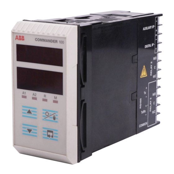
Summarization of Contents
Introduction
MODBUS Option Facilities
Lists the capabilities of the MODBUS communications option for COMMANDER instruments.
Electrical Installation
Host Computer Serial Communications
Describes the requirements for the host computer's serial communication interface.
Two-wire and Four-wire Connection
Details the configuration of serial links for two-wire or four-wire operation.
Pull-up and Pull-down Resistors
Explains the use of resistors to prevent false triggering of slaves.
Termination Resistor
Details the requirement for a 120-ohm termination resistor on long transmission lines.
Serial Connections
Covers connecting multiple slaves and cable length guidelines.
Configuration
Accessing the Configuration Mode
Describes how to enter the configuration mode using a security switch.
Setting the Serial Transmission Parameters
Explains how to set baud rate and parity for serial communication.
Setting the MODBUS Address
Details how to assign a unique MODBUS address to each slave instrument.
MODBUS Protocol
4.1 Introduction
Explains the master/slave principle and broadcast address in MODBUS communication.
4.2 MODBUS Function Codes
Describes the function codes used to instruct the slave on the action to perform.
MODBUS Functions
5.1 Read Coil Status – Function Code 01
Explains how to read the ON/OFF status of discrete outputs from the slave.
5.2 Read Holding Register – Function Code 03
Describes how to read data from holding registers in the addressed slave.
5.3 Force Single Coil – Function Code 05
Explains how to force a single coil ON or OFF.
5.4 Preset Single Register – Function Code 06
Describes how to modify the contents of a holding register.
5.5 Loopback Test – Function Code 08
Details the procedure for testing the MODBUS system.
5.6 Write Multiple Registers – Function Code 16
Explains how to change the contents of up to eight holding registers at once.
Exception Responses
Examples
Provides examples of exception responses sent by the slave for error conditions.
Addressable Parameters
COMMANDER 100/V100 – Coils
Lists the coils (discrete points) and their corresponding variable labels for COMMANDER 100/V100.
COMMANDER 100/V100 – Registers
Lists the registers and their variable labels for COMMANDER 100/V100.
Control Settings
Lists registers related to control settings like set points and output states.
Set Points
Details registers for various set point configurations.
Alarm Settings
Lists registers for configuring alarm trip points and types.
Ramp/Soak Settings
Details registers for managing ramp/soak program execution.
COMMANDER 150/160 – Coils
Lists the coils (discrete points) for COMMANDER 150/160 instruments.
COMMANDER 150/160 – Registers
Lists the registers for COMMANDER 150/160 instruments.
Totalizer Settings
Details registers for totalizer settings.
Maths Functions
Lists registers for process variable calculations.
Customer Support
Client Warranty
Outlines documentation requirements for warranty claims and equipment storage conditions.


Need help?
Do you have a question about the COMMANDER 160 and is the answer not in the manual?
Questions and answers