Table of Contents
Advertisement
Quick Links
Advertisement
Table of Contents

Related Manuals for ABB UNITROL 1005-0011 ECO


Summary of Contents for ABB UNITROL 1005-0011 ECO
- Page 1 AUTOMATIC VOLTAGE REGULATORS UNITROL® 1005 User manual...
- Page 2 UNITROL 1000 Comm-Instruction and PID Tuning (3BHS399489 E01) Power System Stabilizer functionality (3BHS399490 E01) CMT1000 PSS Tuning assistant (3BHS399490 E02) Software revisions Product Release 6.3xx DSP Control: 6.3xx MCU Control: 6.3xx CMT 1000: 6.3xx © 2022 ABB. All Rights Reserved. 3BHS581681 E81 Rev E Effective: 2022-01-10...
-
Page 3: Table Of Contents
TABLE OF CONTENTS Table of contents 1. Introduction ..........................7 1.1 Intended audience ..........................7 1.2 Related documents ..........................7 1.3 Copyright and content information ....................7 1.4 Generic disclaimer ..........................7 1.5 Cyber security disclaimer ........................8 1.6 Documentation, software and tools ....................8 1.6.1 How to register to the myABB business portal .............. - Page 4 TABLE OF CONTENTS 5.7 Inrush current limitation ........................28 5.7.1 External MCB requirements ....................28 5.8 Device connections ..........................29 5.8.1 Power and measurement terminals ..................30 5.8.2 Digital and analog I/O terminals ..................31 5.9 Terminal and signal data ......................... 33 5.10 Communication ports ........................36 5.10.1 USB port ..........................36 5.10.2 Ethernet port .........................
- Page 5 TABLE OF CONTENTS 7.5.2 EEPROM status indicator ......................59 7.6 Menu structure ..........................60 7.6.1 File menu ...........................60 7.6.2 Monitor menu .......................... 61 7.6.3 Setup menu ..........................65 7.6.4 Communication menu ......................68 7.6.5 Tune menu ..........................68 7.6.6 Help menu ..........................70 7.7 Additional tools ..........................71 7.8 Set the AVR-ID and channel identification ...................
- Page 6 TABLE OF CONTENTS 10.2.6 Machine is not stable in parallel to the grid operation ..........96 10.3 Defective unit ...........................96 11. Technical data ........................... 97 11.1 Dimensions ............................97 11.2 Electrical data ...........................98 11.3 Environmental data ........................102 11.4 Markings ............................103 11.5 UL certification (pending) ......................103 11.6 Reliability ............................
-
Page 7: Introduction
Refer to the inner front cover. 1.3 Copyright and content information ABB reserves all rights to this document and to the information and topics contained in it. This also applies to any possible claims to copyright or patents. Forwarding and/or the duplicating of this document without the express permission of ABB is forbidden. -
Page 8: Cyber Security Disclaimer
Notwithstanding any other provision to the contrary and regardless whether the contract is terminated or not, ABB, its subcontractors, its and their affiliates and its and their employees are under no circumstances liable for and the Customer shall defend and... -
Page 9: How To Register To The Myabb Business Portal
1. Select Sign up below the LOGIN button. 2. Fill in the registration form. 3. Select Sign up. 4. ABB sends you an email to activate your ABB account. 5. In the email, select ACTIVATE ACCOUNT. 6. You now have access to the myABB business portal. -
Page 10: Support Information
1.7 Support information If you have questions, contact your local ABB representative or the manufacturer: Note! When you call ABB, please give your name, department and phone number. This allows the responsible ABB representative to call back without delay. ABB Switzerland Ltd... -
Page 11: Terms And Abbreviations
INTRODUCTION 1.8 Terms and abbreviations Term Description Alternating current AI, AO, AIO Analog input, analog output, analog input and output AUTO Automatic voltage regulation (Auto mode) Automatic voltage regulator Batt Battery Controller-area network Circuit breaker CMT 1000 Commissioning and maintenance tool Current transformer Direct current DI, DO, DIO... - Page 12 INTRODUCTION Term Description Power system stabilizer Potential transformer Pulse-width modulation Reactive power Rotating diode monitoring Synchronous machine Software UMAUX UM auxiliary input measurement Reactive power V/Hz Volt per Hertz (-Limiter) Voltage droop compensation Voltage matching...
-
Page 13: Safety
2. Safety Obey the safety instructions in this document when you install, operate and do maintenance on the excitation system. Failure to obey the safety instructions increases the risk of electric shock and damage to the equipment. DANGER • Obey the safety instructions to prevent injury or death, or damage to the equipment. -
Page 14: Warning Symbols
SAFETY 2.1.1 Warning symbols The symbols in warnings identify the type of warning. Example warning symbols: General warning – Conditions, other than those caused by electricity that can cause injury or death, or damage to the equipment. Electricity warning – Electrical hazards that can cause injury or death, or damage to the equipment. -
Page 15: Safety Instructions
SAFETY 2.3 Safety instructions Obey these safety instructions when you do any work on the equipment: • Use the device only as specified in the technical data (refer to Technical data on page 97) and when it is fully operational. •... -
Page 16: Residual Danger Areas
SAFETY 2.3.2 Residual danger areas When the AVR operates, • The voltage in the power section can be up to 300 V AC and the short-circuit current is very high. • The voltage in the control cabinet is > 50 V. When the AVR is disconnected from power supplies, the large capacitors in the AVR hold a charge for some time. -
Page 17: Instructions For Emergency Situations
SAFETY 2.4 Instructions for emergency situations Obey the safety instructions in this section for the specific emergency situations. 2.4.1 Firefighting DANGER In case of fire, be aware of dangerous voltages, toxic gases and overheating. All personnel must know the location of fire extinguishers and emergency exits and must be able to operate the fire extinguishers. -
Page 18: Pacemaker
SAFETY 2.4.3 Pacemaker DANGER Do not stay close to the excitation system. The electrical and magnetic fields of the excitation system can cause malfunctions of pacemakers. Electrical and magnetic fields can cause interference to pacemakers. It is difficult to predict the sensitivity of pacemakers to interference. -
Page 19: Device Overview
3. Device overview The automatic voltage regulator (AVR) is used for the excitation of indirectly excited synchronous machines. The AVR can operate as a voltage regulator, a reactive power regulator, power factor regulator or field current regulator, and is designed for excitation currents of up to 5 A nominal. -
Page 20: Status Leds
DEVICE OVERVIEW 3.1.1 Status LEDs Color Description Green Operating status ON: Device controller is active Flashes: Device software is active Yellow Excitation status ON: Excitation is active Flashes: A limiter is active Alarm status ON: An alarm or a trip is active Flashes: •... -
Page 21: Software Overview
Open Loop mode 3.3.2 Software options You can select a software package that has a default set of software options. To enable more software options, send a password request to ABB. For more information, refer to Software options on page 44. -
Page 22: Mechanical Installation
2. Make sure that all of the listed items are in the product package. 3. Visually examine the AVR to make sure that it does not have any external damages. If the product package has a damage, speak to your local ABB representative. Do not use a product that has a damage. -
Page 23: Installation Area
MECHANICAL INSTALLATION 4.2 Installation area Install the AVR in an indoor area that is dry and dust-free, and that does not contain volatile gases, acid fumes or similar hazards. Examine the installation area and refer to Technical data on page to make sure that: •... -
Page 24: Mechanical Installation Procedure
MECHANICAL INSTALLATION 4.4 Mechanical installation procedure WARNING Obey the safety instructions in on page to prevent injury or death, or Safety damage to the equipment. WARNING Before you start the installation, make sure that the AVR is disconnected from all power sources. -
Page 25: Electrical Installation
5. Electrical installation This chapter gives instructions for the electrical installation of the AVR. WARNING Obey the safety instructions in on page to prevent injury or death, or Safety damage to the equipment. WARNING Before you start the installation, make sure that the AVR is disconnected from all power sources. -
Page 26: Connection Diagram
ELECTRICAL INSTALLATION 5.2 Connection diagram Simplified connection diagram for the AVR. Description Description Digital I/Os Measurement and control unit (DSP) Maximum cable length 30 m Analog I/Os Power electronic control (PWM) Maximum cable length 30 m Network voltage measurement U Communication micro-controller unit (MCU) Machine voltage measurement U... -
Page 27: Excitation Cabling Requirements
ELECTRICAL INSTALLATION 5.3 Excitation cabling requirements The excitation cables refer to the power and measurement cables at terminals 1-15. The system obeys the emission limits of standard EN 61000-6-4 if the connections for the power electronics supply and the field output use shielded cables that are grounded at each end. -
Page 28: Grounding (Pe) Requirements
ELECTRICAL INSTALLATION 5.6 Grounding (PE) requirements Connect the AVR to the protective earth at terminal 1 with a 4 mm grounding wire. Make an additional ground connection through the mounting holes to the installation plate (if it is connected to the protective earth) or with a 4 mm cable to the protective earth. -
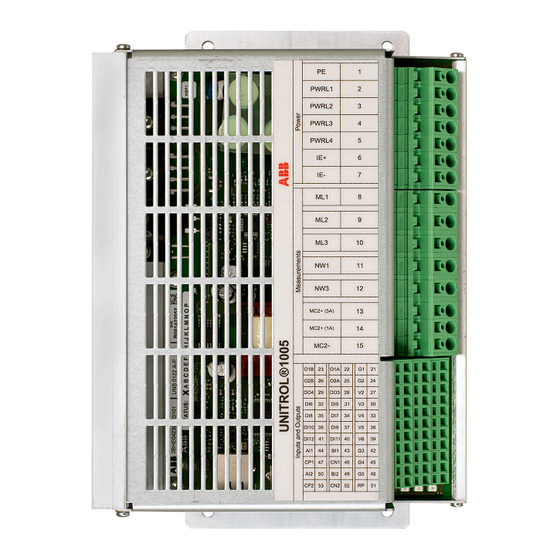
Page 29: Device Connections
ELECTRICAL INSTALLATION 5.8 Device connections Overview of the AVR terminals and connection ports. No. Description Power terminals Measurement terminals Digital and analog I/Os Ethernet port USB port... -
Page 30: Power And Measurement Terminals
ELECTRICAL INSTALLATION 5.8.1 Power and measurement terminals Terminal descriptions for the power and measurement terminals of the AVR. Power and measurement terminals Type Ref. Label Description Protective earth PWR L1 Input power L1 PWR L2 Input power L2 PWR L3 Input power L3 PWR L4 Input power L4... -
Page 31: Digital And Analog I/O Terminals
ELECTRICAL INSTALLATION 5.8.2 Digital and analog I/O terminals Terminal descriptions for the digital and analog I/O terminals of the AVR. Type Ref. Label Description GND, connected to PE (PELV) Digital output 1, potential-free, positive Digital output 1, potential-free, negative GND, connected to PE (PELV) Digital output 2, potential-free, positive Digital output 2, potential-free, negative 2 V output, connected to other Vx (PELV) - Page 32 ELECTRICAL INSTALLATION Type Ref. Label Description Analog ground, connected to PE (PELV) Analog input 1, negative (PELV) Analog input 1, positive (PELV) Analog ground, connected to PE (PELV) Configuration terminal for 20 mA input (PELV) Configuration terminal for 20 mA input (PELV) Analog I/O terminals Analog ground, connected to PE (PELV)
-
Page 33: Terminal And Signal Data
ELECTRICAL INSTALLATION 5.9 Terminal and signal data The table lists the terminal and signal data, and gives a circuit description. Terminal Signal Circuit description 1 = PE Protective earth Power electronics and control Absolute max. values supply U 2 = PWR L1 •... - Page 34 ELECTRICAL INSTALLATION Terminal Signal Circuit description Line voltage measurement single- 11 = NW1 phase U External 12 = NW2 • Network L1 • Network L3 max. 500 V / 0.2 VA 1) You must ground PTs and CTs. Digital output, potential-free External 22 = OA1 •...
- Page 35 ELECTRICAL INSTALLATION Note! The internal 24 V supply (V1 to V6) can be loaded with a maximum of 50 mA by all used digital inputs and outputs. If the power consumption is higher, use an external power supply. Terminal Signal Circuit designation Analog inputs ±10 V DC AIx/BIx...
-
Page 36: Communication Ports
ELECTRICAL INSTALLATION 5.10 Communication ports The AVR has two communication ports that you can use at the same time: • The USB port connects the AVR to the PC with a USB cable. CMT 1000 uses the USB for communication with the AVR. •... -
Page 37: Ethernet Port
ELECTRICAL INSTALLATION 5.10.2 Ethernet port Use the Ethernet port to connect the AVR to a multi-point network. You can monitor and control the AVR from a remote location. In an Ethernet network you can use remote access with the Modbus TCP protocol. You can also connect the AVR directly to a PC with the Ethernet connection. -
Page 38: Device Software
6. Device software This chapter gives a description of the device software: the control modes and setpoints, available software options, and digital and analog I/O signals. For information on the control features of the device software, refer to the Control SW manual (3BHS399489 E02). -
Page 39: Open Loop Mode
DEVICE SOFTWARE 6.1.5 Open Loop mode • Overrides the excitation output of the AVR • Set a defined AVR output for commissioning and identification of system data • The excitation voltage (U ) is directly defined by the multiplication of the PWM signal with the rectified input voltage of the AVR (U Note! Limiters are not active in Open Loop mode. -
Page 40: Priority Of Control Modes
DEVICE SOFTWARE 6.2 Priority of control modes The priority of control modes defines which signal overrides another signal. Priority 1 is the highest priority. For example, if the digital input “Standby” is active, all other digital inputs of the control modes are ignored. The priority of control modes: Generator states NoLoad... -
Page 41: Setpoints Of The Control Modes
DEVICE SOFTWARE 6.3 Setpoints of the control modes You can adjust the setpoints in the Setup menu > Setpoints. The control modes have the setpoint parameters that follow: • Minimum • Maximum • Ramp rate • Initial setpoint 6.3.1 Initial setpoint An initial setpoint is used: •... -
Page 42: Reset Setpoint
DEVICE SOFTWARE 6.3.3 Reset setpoint When the signal “Reset Setpoint” is active: • The setpoint of the control mode goes to the value that follows in accordance with the defined ramp rate: Control mode Final value Manual No load Open Loop 100 % 1/Kceil Auto 100 %... -
Page 43: Select A Control Mode
DEVICE SOFTWARE 6.4 Select a control mode To select a control mode: Make sure that CMT 1000 has control access. 2. Open the Setup menu. 3. Select Digital I/Os. 4. Select the correct digital inputs to activate a control mode. For example, to activate PF mode, select PF Enable and, if necessary, select Gen CB Closed Status or Parallel with Grid Status. -
Page 44: Software Options
A set of software options is enabled by default in each AVR. It is possible to enable more software options that extend the capabilities of the AVR. To enable a software option, send a request for a password to your ABB representative. For instructions on how to enable a software option, refer to Enable a software option page 45. -
Page 45: Enable A Software Option
Use CMT 1000 on your PC to enable software options in the AVR. Note! It is necessary to have a password for each additional software option. Send a request for a password to your ABB representative. For more information, refer Support information on page 10. -
Page 46: Digital Inputs
DEVICE SOFTWARE 6.6 Digital inputs Digital input signal Description Input not assigned None Excitation ON command active: Excitation ON • Field Flashing starts, if Off Level > 0 % • Auto mode: Soft Start starts after the Off Level is reached, and increases until the Initial setpoint value of Auto mode. - Page 47 DEVICE SOFTWARE Digital input signal Description Activates the direct control of a power transistor: Open Loop Enable Overrides AVR output. Synchronize Activates Voltage Matching: (Requires the Synchronization software option) The input signal activates Voltage Matching only. Clears the alarms that follow: Reset Alarm •...
-
Page 48: Digital Outputs
DEVICE SOFTWARE 6.7 Digital outputs Digital output signal Description Output not assigned None Boost status signal is active: Boost • Boost supports the excitation if there is a short-circuit current or heavy load in the network • Boost is configured to trigger at a defined threshold of the machine voltage •... -
Page 49: Polarity And Forcing Digital Signals
DEVICE SOFTWARE Digital output signal Description An alarm indication of an open diode Diode Alarm • Detection of an open diode on the rotor of the machine • Depends on the settings for rotating diode monitoring Diode Trip A trip indication of a shorted diode •... -
Page 50: Analog Inputs
DEVICE SOFTWARE 6.9 Analog inputs Analog input signal Description Input not assigned None External setpoint to Auto mode Auto Remote Setpoint ±10 V / 0 - 20 mA PF Remote Setpoint External setpoint to PF mode ±10 V / 0 - 20 mA External setpoint to VAR mode VAR Remote Setpoint ±10 V / 0 - 20 mA... -
Page 51: Voltage Level Of The Analog Inputs
DEVICE SOFTWARE 6.9.1 Voltage level of the analog inputs You can set a minimum and maximum voltage level for each analog input. Uin0% Uin100% Minimum Maximum Analog input signal Remarks input voltage input voltage (-10 - +10 V) (-10 - +10 V) Auto Remote Setpoint Auto setpoint Auto setpoint... -
Page 52: Double Channel (Dch) Software
DEVICE SOFTWARE 6.9.1.2 Input voltage to the summing point UM Aux Uin0% Analog in Uin100% 6.9.1.3 Requirements for DI13 to DI18 Requirements for analog inputs that are used as digital inputs (DI13 to DI18): DI13(+) DI13 = 1 DI14(-) DI13 = 0 -5.0 -2.0 DI14 = 0... -
Page 53: Configuration
DEVICE SOFTWARE Cyber security note: Modbus does not natively guarantee secure communication. Any node that is able to communicate with the AVR via Modbus can perform unwanted changes or incorrect configurations on such products that can disrupt the intended operation of the AVR and the systems connected to it. It is recommended to limit the Modbus communication within trusted networks and to strictly control access to such networks. -
Page 54: Commissioning And Maintenance Tool Cmt 1000
CMT 1000 is a PC application to adjust the settings of your AVR. Connect your PC to the AVR with a USB or Etherner connection. ABB recommends a USB connection for the initial installation and an Ethernet connection for control use. -
Page 55: Install Cmt 1000
COMMISSIONING AND MAINTENANCE TOOL CMT 1000 7.3.1 Install CMT 1000 To install the CMT 1000 software: Make sure that you have the correct revision of the CMT 1000 software (3BHS346676). Note that you can open parameter files only with a compatible software revision. 2. -
Page 56: Starting Procedure
COMMISSIONING AND MAINTENANCE TOOL CMT 1000 7.4 Starting procedure It is necessary to set a connection type before communication with the AVR is possible. Follow the starting procedure: Set a connection type (refer to Set a connection type on page 56). 2. -
Page 57: Scanning Process
COMMISSIONING AND MAINTENANCE TOOL CMT 1000 7.4.1.2 Connection through the Ethernet port Select the TCP/IP tab. 2. Enter the IP address of the remote terminal in the Remote IP Address field. 3. A pinging process starts automatically. After two seconds CMT 1000 shows a message: •... -
Page 58: Communication With The Avr
COMMISSIONING AND MAINTENANCE TOOL CMT 1000 7.5 Communication with the AVR CMT 1000 has three access levels to connect to an AVR: off-line, monitor access and control access. You can communicate with the AVR only during monitor access or control access. When off- line, CMT 1000 can only read the AVR-ID and channel identification (Main or Redundant) directly from the AVR. -
Page 59: Eeprom Status Indicator
COMMISSIONING AND MAINTENANCE TOOL CMT 1000 7.5.2 EEPROM status indicator The EEPROM status indicator shows if the parameter values agree in the RAM and in the non- volatile memory (EEPROM) of the AVR. The color of the EEPROM status indicator changes (on and off): No. -
Page 60: Menu Structure
COMMISSIONING AND MAINTENANCE TOOL CMT 1000 7.6 Menu structure The main window of CMT 1000 has 6 menus, where you can get access to all of the software features. Each menu item is in a group in accordance to its functionality. Overview of the menus: •... -
Page 61: Monitor Menu
COMMISSIONING AND MAINTENANCE TOOL CMT 1000 File menu items: • Open Parameter File: Open a parameter file from the hard disk of the PC • Save Parameter File: Save a parameter file to the hard disk of the PC • Write Parameters to EEPROM: Save the parameters to the non-volatile memory (EEPROM) of the AVR •... - Page 62 COMMISSIONING AND MAINTENANCE TOOL CMT 1000 7.6.2.1 Measurements The Measurements window shows the measurements of the AVR. 7.6.2.2 Oscilloscope The Oscilloscope window shows a visualization of 6 signals at a time (out of 21 signals). For more information, refer to Oscilloscope on page 79.
- Page 63 COMMISSIONING AND MAINTENANCE TOOL CMT 1000 7.6.2.3 PQ Diagram (Power chart) The PQ Diagram window shows the measurements of reactive power Q (on the x-axis) and active power P (on the y-axis) in relation to the machine voltage. The white arrow (at the bottom of the figure) shows the current operating point when the synchronous machine is connected to the grid.
- Page 64 COMMISSIONING AND MAINTENANCE TOOL CMT 1000 7.6.2.5 I and I Temperature Monitor The I Temperature Monitor and I Temperature Monitor windows show the measurements of machine current (I ) and excitation current (I ) in relation to the cooling temperature. 7.6.2.6 Second Channel Measurements The Second Channel Measurements window shows the measurements from the second channel (Redundant) in a Double Channel system.
-
Page 65: Setup Menu
COMMISSIONING AND MAINTENANCE TOOL CMT 1000 7.6.2.7 History Logger The History Logger window shows visualization of history logs from the AVR. For more information, refer to History Logger on page 86. 7.6.3 Setup menu... - Page 66 COMMISSIONING AND MAINTENANCE TOOL CMT 1000 Setup menu items: • System Data: Set parameters for system data • Soft Start: Set parameters for Soft Start ramp • Field Flashing: Settings for Field Flashing • Motor Excitation: Settings for Motor Excitation •...
- Page 67 COMMISSIONING AND MAINTENANCE TOOL CMT 1000 Limiters menu items: • V/Hz Limiter: Configuration of V/Hz limiter • Operational Limits: Configuration of PQ, U and I limiters • Boost and FRT detection: Line short-circuit support and fault ride through • Temp Influence: I and I limiters temperature influence 7.6.3.2 Setup >...
-
Page 68: Communication Menu
COMMISSIONING AND MAINTENANCE TOOL CMT 1000 7.6.4 Communication menu Communication menu items: • ID Definition: Set the AVR-ID (for VDC) and the channel identification (for DCH) • Port Configuration: Configuration of a serial COM port or TCP/IP address • AVR Ethernet Settings: Settings for the Ethernet communication •... - Page 69 COMMISSIONING AND MAINTENANCE TOOL CMT 1000 7.6.5.1 Setpoint Adjust The Setpoint Adjust window includes a visualization of the control modes, generator states, limiters and alarm status. Here you can adjust setpoints and do step response tests. Note! It is recommended to keep the Setpoint Adjust window always open. Generator State shows if the synchronous machine is connected to the grid, a secondary network, a primary network or if it has no load.
-
Page 70: Help Menu
COMMISSIONING AND MAINTENANCE TOOL CMT 1000 7.6.6 Help menu In the Help menu you can update the device software of the AVR and get information on the software revisions. Help menu items: • Firmware update: Update the device software • About CMT 1000: Information on the software revisions of the DSP, MCU and CMT 1000 7.6.6.1 Update the device software CAUTION... -
Page 71: Additional Tools
Click on the window to close it. Note! The serial number of the AVR is shown in the About CMT 1000 window. Please give the serial number to the ABB representative when you make requests for software options. 7.7 Additional tools... -
Page 72: Set A Control Password
COMMISSIONING AND MAINTENANCE TOOL CMT 1000 If you do not use the Double Channel software, you can change the channel identification without an effect on the AVR. However, a change of the channel identification has an effect on the Modbus ID that is used for remote access with CMT 1000. The Modbus slave ID that is used for remote access with CMT 1000 is a number between 1 and 63. -
Page 73: Parameter Files
COMMISSIONING AND MAINTENANCE TOOL CMT 1000 7.11 Parameter files A parameter file contains the parameter values of the AVR. You can examine a parameter file in CMT 1000 or in a text editor. Engineering personnel can prepare a parameter file that contains a set of parameter values for the commissioning of an AVR. -
Page 74: Examine A Parameter File
COMMISSIONING AND MAINTENANCE TOOL CMT 1000 7.11.1 Examine a parameter file To examine a parameter file in CMT 1000: Make sure that CMT 1000 is offline. 2. Open the File menu. 3. Select Open Parameter File. The parameter file opens only in CMT 1000. It does not have an effect on the AVR. -
Page 75: Write Parameters To The Non-Volatile Memory (Eeprom) Of The Avr
COMMISSIONING AND MAINTENANCE TOOL CMT 1000 7.11.4 Write parameters to the non-volatile memory (EEPROM) of the AVR CAUTION Save the parameters to the non-volatile memory (EEPROM) of the AVR each time you adjust the parameter values. If the parameters are not saved to the EEPROM, after a power cycle the AVR starts with the previous values. -
Page 76: Prepare A Configuration File
COMMISSIONING AND MAINTENANCE TOOL CMT 1000 7.11.6 Prepare a configuration file You can use a parameter file called “a configuration file” as a reference parameter file for the commissioning of one or more AVRs. To create a configuration file: Make sure that CMT 1000 is offline and not connected to an AVR. 2. -
Page 77: Adjust Digital I/Os
COMMISSIONING AND MAINTENANCE TOOL CMT 1000 7.12 Adjust digital I/Os You can: • Set digital inputs DIO1 to DIO8 as input and output at the same time. • Use digital inputs DI13 to DI18 as virtual digital inputs. They are not set as digital inputs in the analog inputs section. -
Page 78: Set An Analog Input As A Digital Input
COMMISSIONING AND MAINTENANCE TOOL CMT 1000 7.12.1 Set an analog input as a digital input You can set analog inputs as digital inputs to enable the digital inputs DI13-DI18. To set an analog input as a digital input: Make sure that CMT 1000 has the necessary access level: •... -
Page 79: Oscilloscope
COMMISSIONING AND MAINTENANCE TOOL CMT 1000 7.13 Oscilloscope The Oscilloscope visualizes 6 signals at a time (out of 21 signals in the signal menu). You can examine real-time measurements and saved transient data. You can: • Set signals for visualization (on page 80) •... -
Page 80: Set The Signals
COMMISSIONING AND MAINTENANCE TOOL CMT 1000 Oscilloscope menu items: When you use the Oscilloscope, it is recommended to have these windows open: • Measurements • Setpoint Adjust • Monitor and Protection • Digital I/Os • Applicable instruments, such as PQ Diagram and Tune windows 7.13.1 Set the signals To set a signal in the Oscilloscope: Open the Monitor menu in the main window of CMT 1000. -
Page 81: Save A Setup
COMMISSIONING AND MAINTENANCE TOOL CMT 1000 2. In the bottom of the Oscilloscope window, select the box next to Buffer Length. 3. To change the value, select the arrow down or up. You can select a predefined value: 1, 2, 5, 10, 20, 50, 100, 200 or 500 seconds. -
Page 82: Save A Waveform File
COMMISSIONING AND MAINTENANCE TOOL CMT 1000 7.13.6 Save a waveform file To save a waveform file: In the Oscilloscope window, open the File menu. 2. Select Save Waveform. 3. Select a location on your PC. 4. Enter a file name. 5. - Page 83 COMMISSIONING AND MAINTENANCE TOOL CMT 1000 7.13.8.2 Examine a saved waveform file The recorded data in a saved waveform file includes all of the 21 signals that you can select. Open other instruments to see the data. Some data is shown in the right side section of the Oscilloscope.
-
Page 84: Analog Status Signals
COMMISSIONING AND MAINTENANCE TOOL CMT 1000 An example of a sweep buffer: 7.13.9 Analog status signals There are 4 analog signals that show status changes on the Oscilloscope. The decoding of those signals is explained as follows: Generator GenState AlarmTripStatus Combined Limit Control Mode Signal Name... -
Page 85: Problems With The Oscilloscope
COMMISSIONING AND MAINTENANCE TOOL CMT 1000 Generator GenState AlarmTripStatus Combined Limit Control Mode Signal Name Signal Name Signal Name Signal Name Maximum Change Diode Alarm Machine Secondary active Voltage Net -> (requires Limiter active NoLoad RDM SW) (Max U Sync Reserved Primary Net Diode Trip... -
Page 86: History Logger
COMMISSIONING AND MAINTENANCE TOOL CMT 1000 7.14 History Logger History Logger records the last two hours of operation. Measurements from 12 defined signals are stored every minute in the non-volatile memory (EEPROM) of the AVR. History Logger requires the History Logger software. You can use cursor A to show the data on the six measurement channels on the right. -
Page 87: Open A History Log From Your Pc
COMMISSIONING AND MAINTENANCE TOOL CMT 1000 7.14.1 Open a history log from your PC To open a saved history log file from your PC: Make sure that CMT 1000 is off-line. 2. On the right side of the main window of CMT 1000, select CMT 1000 for UNITROL 1020. 3. -
Page 88: Commissioning
8. Commissioning This chapter gives an overview of the commissioning procedure. Only certified personnel can do commissioning of the AVR. Make sure to read and obey the safety instructions on Safety on page 13. For full instructions on how to do the commissioning of the AVR, refer to the UNITROL 1000 Com-Instructions and PID tuning (3BHS399489 E01). -
Page 89: Commissioning Procedure
COMMISSIONING 8.2 Commissioning procedure This section provides an overview of the commissioning procedure. For detailed instructions on commissioning, refer to UNITROL 1000 Com-Instructions and PID tuning (3BHS399489 E01). Commissioning procedure overview: Make sure that all of the connections are correct and safe. 2. -
Page 90: Operation
13. Only qualified personnel are permitted to operate the AVR. Operating personnel must be familiar with the excitation system and the related safety hazards. Note! ABB recommends periodical training for operating personnel. DANGER Dangerous voltage. There is a risk of electric shock. -
Page 91: Priority Of The Operators
More than 10 independent remote access connections try to connect to the same AVR Note! If these limitations are surpassed, one or all of the connected operators can lose their access and go off-line. This practice is not recommended by ABB. -
Page 92: Troubleshooting
10. Troubleshooting This chapter gives instructions on how to find faults in the excitation system. Note that this chapter does not fully include all possible faults. Before you start to do work on the excitation system, make sure that you read and understand the safety instructions in Safety on page 13. -
Page 93: Machine Voltage Cannot Ramp Up
TROUBLESHOOTING Fault Cause/Indication Procedure Excitation is not on. Excitation is blocked. Make sure that: Setpoint Adjust window • Emergency Excitation OFF shows a red background on digital input is not active the active mode. • Start frequency is reached as defined in Soft Start •... -
Page 94: Machine Overvoltage After Start-Up
TROUBLESHOOTING Fault Cause/Indication Procedure Machine voltage cannot Machine voltage cannot Examine the initial setpoint ramp up after you have ramp up because of the settings. examined the above- initial setpoint settings. Make sure that the initial mentioned points and setpoint is more than 0 %. setpoints. -
Page 95: The Voltage Is Not Stable In No-Load Operation
TROUBLESHOOTING 10.2.4 The voltage is not stable in no-load operation Fault Cause/Indication Procedure Bad voltage regulation. Tuning is not done correctly. Do a step response test and examine the result with the Oscilloscope to examine the tuning of the AVR. Use the PID tuning assistant to get a correct tuning. -
Page 96: Machine Is Not Stable In Parallel To The Grid Operation
Upload a parameter file to your PC If the AVR is defective, send it to the service center with a detailed description of the fault or failure. Contact ABB for information on your local service center. Refer to Support information... -
Page 97: Technical Data
11. Technical data This chapter gives the technical data of the AVR. 11.1 Dimensions Dimensions and weights Weight... -
Page 98: Electrical Data
TECHNICAL DATA 11.2 Electrical data Electrical data of the power and measurement terminals Power supply input (AC/DC) AC nominal voltage (sinusoidal) 16 - 250 V AC Maximum 300 V AC AC voltage (maximum sinusoidal) Frequency 40 - 600 Hz DC nominal voltage 25 - 300 V DC Maximum DC voltage 420 V DC... - Page 99 TECHNICAL DATA Electrical data of the power and measurement terminals Derating factor (m.a.s.l. >1000 m) For installation altitude higher than 1000 m kH = 1 - 85.7 E (h - 1000 m) above sea level, a derating factor (kH) applies to the nominal excitation current (Ie).
- Page 100 TECHNICAL DATA Electrical data of the power and measurement terminals Maximum current for 10 s (1 A) 4 A rms Maximum current for 1 s (1 A) 8 A rms Maximum current for 10 s (5 A) 22 A rms Maximum current for 1 s (5 A) 38 A rms Accuracy...
- Page 101 TECHNICAL DATA Electrical data of the analog and digital inputs and outputs Accuracy < +/- 1 % Resolution 0.1 mA Digital inputs Number of inputs Input impedance to GND 2.2 kOhm GND reference Input voltage range 0 - 28 V Digital input thresholds (high/low) 13 V / 5 V Digital outputs, isolated...
-
Page 102: Environmental Data
TECHNICAL DATA Electrical data of the communication interfaces USB version 1.0, 2.0 11.3 Environmental data Environmental data Permitted ambient temperature Maximum storage temperature 0 - 55 °C Recommended storage temperature 25 °C Operating temperature -40 - 70 °C Maximum heat sink temperature 90 °C Mechanical stability Vibration, IEC60068-2-6... -
Page 103: Markings
TECHNICAL DATA 11.4 Markings CE marking DNV.COM/AF 11.5 UL certification (pending) To use the AVR in a UL compliant way, obey these rules: • Maximum ambient temperature is 70 °C. • Maximum output capability at 70 °C 5 A / 150 V •... -
Page 104: Storage And Recycling
11.7.1 Storage conditions Put the unit to storage in the original product package. Make sure that the environmental conditions are in the permitted range during storage. ABB recommends to keep the ambient temperature and the relative air humidity constant. Refer to... -
Page 105: Ordering Information
Remove dangerous materials and components that can cause damage to the environment. 2. Put the unit in a shredding machine. 3. The unit is mechanically shredded into small pieces. 4. Recycle the materials. 11.8 Ordering information Description Order code Order text UNITROL 1005-0011 ECO 3BHE043576R0011 UNITROL 1005-0012 LIGHT 3BHE043576R0012... -
Page 106: Settings Record For The Avr
TECHNICAL DATA 11.9 Settings record for the AVR Settings record Name and address of customer Plant Order No. Plant schematic No. Device identification Type plate Delivery date Software revision Device software CMT 1000 Remarks Place and date of commissioning Name Company... - Page 107 For more information, visit abb.com/unitrol © 2022 ABB. All Rights Reserved. Specifications subject to change without notice.
Need help?
Do you have a question about the UNITROL 1005-0011 ECO and is the answer not in the manual?
Questions and answers