
Related Manuals for Hunter G900 Series


Summary of Contents for Hunter G900 Series
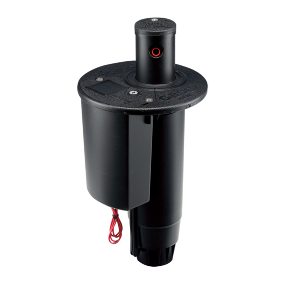
- Page 1 TTS GOLF ROTOR OWNERS MANUAL GOLF IRRIGATION Built on Innovation ® hunterindustries.com...
- Page 2 Inlet Valve Installation – G900 Series and pleasing to the eye.This manual covers all aspects of installation, operation and servicing for Hunter’s TTS rotors including models G835, G870, G875, G880, G884 , G885, G990 Nozzle Replacement – G70 Risers Solenoid, Pilot Valve & Regulator Servicing and G995.
- Page 3 G800E = a G800 body in a VIH valve configuration • G800 Series rotors with nozzles #2 thru #18 - • Replace the final fitting of the existing swing G884 = G800 body style fitted with a G84 G800D = a G800 body in a DIH valve configuration 1”...
- Page 4 If specified or requested T-Handle Tool – PN 053191 Hunter Wrench – PN 172000 otherwise, the solenoid lead wires and controller Snap-ring Tool – PN 052510 field wires can be pulled up into the rotor’s The ON-AUTO-OFF selector’s function and...
- Page 5 Find the end of the ⅛ inch tubing that comes into the flange compartment from the bottom of the rotor (FIGURE 4). UPPER SNAP-RING REMOVAL – G800 SERIES Check-O-Matic (“C”) versions of TTS rotors can be converted for use in Normally Open Hydraulic systems by removing the end cap on the ⅛...
- Page 6 Insert the the socket’s shape (FIGURE 18). G990 and G995 Hunter Wrench, T-Handle Tool or tip of the risers have a removable rubberized logo cap so Once the rubberized logo cap is removed, use the heel on the palm of your hand to forcefully press Snap Ring tool into the riser’s lift socket, turn ¼...
- Page 7 ARC ADJUSTMENT PREPARATION – G35, G75, G85 & G95 PART-CIRCLE RISERS ARC ADJUSTMENT PROCEDURE – G35, G75 & G95 ADJUSTABLE PART-CIRCLE RISERS All Hunter adjustable arc rotors have a fixed stop on the right side of the arc and an adjustable stop All adjustments are initiated by inserting the stop turning or, a ratcheting sound will be heard.
- Page 8 On the G35 or G75 rubberized logo cap, locate the nozzle. Lower the setscrew in front of the the nozzles (FIGURE 29). Insert the metal end of the Hunter wrench or a inch wrench into the the arrowhead shaped area directly above the nozzle only as far as necessary to prevent membrane within the arrow that is directly above the nozzle to be replaced.
- Page 9 downward and then holding riser firmly to the Hunter wrench or a inch wrench into prevent the spring from moving upwards. setscrew that is above the nozzle to be replaced.
- Page 10 Take care not to position the nozzle as the removal process can damage the nozzle and negatively affect the performance. the metal end of the Hunter wrench or a setscrew in front of or against the nozzle’s orifice inch wrench into setscrew that is above the as its performance can be negatively affected.
- Page 11 rubberized logo cap close to the “H” and the “r” on the Hunter logo (FIGURE 44 & 45). The Phillips compressed retraction spring are retained on grabbing the riser seal-block assembly, pressing headed retaining screws are directly beneath these depressions.
- Page 12 RISER SEAL REPLACEMENT I TABLE OF CONTENTS TABLE OF CONTENTS I RISER SEAL REPLACEMENT The riser seal on G80 risers include two primary components - the seal block assembly and the Slide the new face-seal down and onto the riser. To install the nozzle housing’s shroud/logo-cap face-seal.
- Page 13 RISER SEAL REPLACEMENT I TABLE OF CONTENTS TABLE OF CONTENTS I RISER FILTER SCREEN SERVICING RISER FILTER SCREEN SERVICING – ALL TTS ROTORS The riser seal on G90 and G95 risers include two primary components - the seal block assembly and the face-seal.
- Page 14 STATOR ADJUSTMENTS I TABLE OF CONTENTS TABLE OF CONTENTS I STATOR ADJUSTMENTS STATOR ADJUSTMENTS – WHY AND WHEN ARE THEY NEEDED? To reset and install the adjustable stator plate, number on the gray stator (FIGURE 59). Then, notice the small cutout on each of the three snap the adjustable stator plate down into The adjustable stator is preset at the factory to match the nozzle installed in the rotor.
- Page 15 Beneath the adjustable stator plate is a black non- be irrigated. All Hunter adjustable arc rotors For convenience of installation, new rotors from removable plastic part with the opening in the center for the turbine and the single opening to the...
- Page 16 To pull the riser assembly above the upper snap-ring’s wiper seal, first locate the lift-up socket on top of the riser assembly. Using the T-Handle Tool or Snap-ring Tool or Hunter Wrench, insert FIGURE 69 FIGURE 70 FIGURE 71 Fig 70 ...
- Page 17 Before the ON position. Warning – rotor may activate for a valves). If the incorrect inlet valve is installed, the rotor will malfunction. Hunter has a color-coding white lower snap-ring and inlet valve can be brief period of time.
- Page 18 G800 Series inlet valves are removed from the body using compartment lid has been removed. Align the the tool’s handle clockwise until it stops.
- Page 19 INLET VALVE REMOVAL I TABLE OF CONTENTS TABLE OF CONTENTS I INLET VALVE REMOVAL Inlet valve removal option 2 – Once the white lower snap-ring has been removed, the inlet valve Once the white lower snap-ring has been tool’s black plastic part. First, look at the top is released and is ready for removal.
- Page 20 INLET VALVE REMOVAL I TABLE OF CONTENTS TABLE OF CONTENTS I INLET VALVE SERVICING To remove the inlet valve, it is necessary to align the pointer arrow on the G900 Valve Tool with INLET VALVE SERVICING – ALL MODELS the alignment dot on the rotor’s flange. The alignment dot is centered on the flange compartment Inlet Valves (also commonly known as foot metal pins on the tool into the holes at the lid adjacent to (next to) the body cavity opening.
- Page 21 (located at of one of the three Inlet valve installation option 1 – G800 Series inlet valves are installed in the body using the G800 G800 Valve Tool correctly. If the snap ring is screws on top of the tool) is also oriented to Valve Tool.
- Page 22 INLET VALVE INSTALLATION I TABLE OF CONTENTS TABLE OF CONTENTS I INLET VALVE INSTALLATION Next, slightly rotate the tool counter-clockwise to the 11:30 position. This alignment will allow the A distinct “click” sound should be heard as the communication port must engage the two metal hooks on the G800 Valve Tool to pass through the two correct openings around the snap ring is released and engages the snap ring communication port at the bottom of the rotor’s...
- Page 23 INLET VALVE INSTALLATION I TABLE OF CONTENTS TABLE OF CONTENTS I INLET VALVE INSTALLATION Next, use the 16” Needle-Nose Pliers Tool to install the white lower snap ring. To do so, use the G900 Series inlet valves are installed in the pointing and alignment features on the tool’s tool to grab the outer side of the two raised areas near the ends of the white lower snap-ring body using the G900 Valve Tool.
- Page 24 INLET VALVE INSTALLATION I TABLE OF CONTENTS TABLE OF CONTENTS I INLET VALVE INSTALLATION Next, place the snap ring on top of the G900 valve as shown (FIGURE 117). Make sure that the Check to make sure that the pointer arrow on As the G900 Valve Tool is lowered into the snap ring’s upper side (thinnest side) is facing upwards.
- Page 25 Solenoid (FIGURE 129). Flat Blade Screwdriver Side Cutters (Dykes) or Blade Cutter Snap Ring Tool - PN 052510 Hunter Wrench – PN 172000 ACCESS TO FLANGE COMPARTMENT COMPONENTS Using a Phillips screwdriver, remove the two stainless steel screws that retain the flange compartment’s lid (FIGURE 124).
- Page 26 There are three ways to prevent activation of the rotor when the Solenoid is removed from the counter-clockwise turns. Pull to separate the Hunter Solenoids. To replace a worn or damaged Pilot Valve: Solenoid from the Pilot Valve (FIGURE 133). The rubberized Seat-Seal, simply pull the old one ①...
- Page 27 If not possible, feed replacement solenoid’s wiring through hole at the bottom of the flange compartment. Splice controller wires with solenoid’s wires using appropriate grease-filled connectors. Choose either of the Hunter DC solenoid’s lead wires when making each splice as there is no specific polarity required.
- Page 28 CONNECTING SOLENOID TO PILOT VALVE I TABLE OF CONTENTS TABLE OF CONTENTS I ATTACHING SOLENOID ASSEMBLY CONNECTING SOLENOID TO THE PILOT VALVE ATTACHING THE ASSEMBLED SOLENOID AND PILOT VALVE TO THE FLANGE COMPARTMENT To ensure that the On-Off-Auto feature functions properly, follow the procedure outlined below. With the Solenoid and Pilot Valve correctly that the rotor’s flange compartment is at the The TTS rotor’s Solenoid has double-lead threads.
- Page 29 ATTACHING SELECTOR CAP TO SOLENOID I TABLE OF CONTENTS TABLE OF CONTENTS I PRESSURE REGULATOR ADJUSTMENT ATTACHING SELECTOR CAP TO THE SOLENOID Pressure regulation also prevents too much Pressure Regulator Settings – All electric pressure from reaching the nozzles. Rotors valve-in-head TTS rotors have adjustable Pressure The Selector Cap turns the Solenoid when the user changes the ON-AUTO-OFF settings.
- Page 30 Place the flange If you have further questions after reviewing compartment lid into position and align the this manual, please contact Hunter’s Technical FIGURE 146 Selector Cap to its hole in the lid. Press the Services Department at 800-733-2823 and flange compartment lid into position and secure select option #3.
- Page 31 Hunter family of customers for years to come. Gregory R. Hunter, President of Hunter Industries Website hunterindustries.com...
Need help?
Do you have a question about the G900 Series and is the answer not in the manual?
Questions and answers