Table of Contents
Advertisement
Service Literature
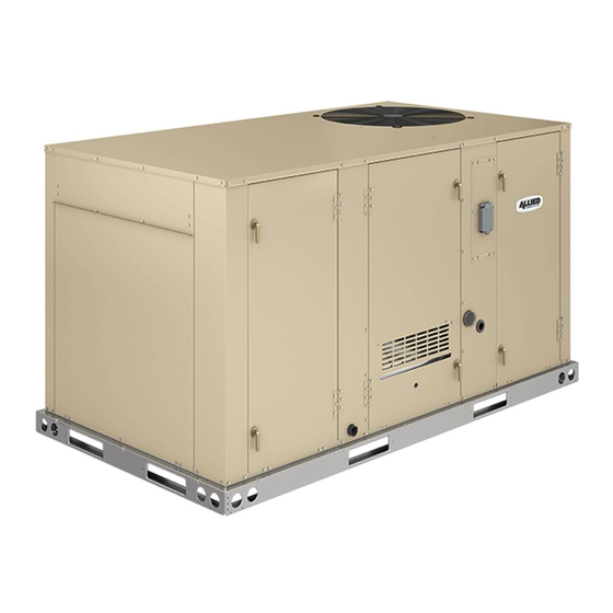
The KGB packaged gas units are available in standard
cooling efficiency (024, 030, 036, 048 060, 072, 074 and
090). Cooling capacities range from 2 to 7-1/2 tons (7 to
26kW).
KGB024, 030, 036, 048, 060, 072, 074 units are avail
able in 65,000 BTUH heat capacity /KGB036, 048, 060,
072, 074 and 090 units are available in 108,000 BTUH
(105,000 BTUH in earlier built units ) heat capacity.
KGB048, 060, 072, 074 and 090 units are available in
150,000 BTUH (44 kW) heat sizes. Two stage heat is
available in units with 108,000 (105,000 in earlier built
units) and 150,000 BTUH capacities. Gas heat sections
are designed with aluminized steel tube heat exchang
ers.
Information contained in this manual is intended for use by
qualified service technicians only. All specifications are
subject to change. Procedures outlined in this manual are
presented as a recommendation only and do not super
sede or replace local or state codes.
If the unit must be lifted for service, rig unit by attaching four
cables to the holes located in the unit base rail (two holes at
each corner). Refer to the installation instructions for the
proper rigging technique.
WARNING
Improper installation, adjustment, alteration, service
or maintenance can cause property damage, person
al injury or loss of life. Installation and service must
be performed by a licensed professional installer (or
equivalent), service agency or the gas supplier.
WARNING
Electric shock hazard. Can cause injury
or death. Before attempting to perform
any service or maintenance, turn the
electrical power to unit OFF at discon
nect switch(es). Unit may have multiple
power supplies.
CAUTION
As with any mechanical equipment, contact with
sharp sheet metal edges can result in personal in
jury. Take care while handling this equipment and
wear gloves and protective clothing.
100004
May 2020
KGB024 through 090
Electrostatic discharge can affect electronic
components. Take precautions during unit instal
lation and service to protect the unit's electronic
controls. Precautions will help to avoid control
exposure to electrostatic discharge by putting
the furnace, the control and the technician at the
same electrostatic potential. Neutralize electro
static charge by touching hand and all tools on an
unpainted unit surface, such as the gas valve or
Blower deck, before performing any service pro
cedure.
Spec. Gas Heat / High Altitude
II Placement and Installation
III Start Up Operation
IV Charging
V System Service Checks
VI Maintenance
VII Accessories
VIII Diagrams
Page 1
KGB SERIES
2 to 7-1/2 ton
7 to 26 kW
ELECTROSTATIC DISCHARGE (ESD)
Precautions and Procedures
CAUTION
Table of Contents
. . . . . . . . . . . . . . . . . . . . . . .
. . . . . . . . . . . . . . . . . .
. . .
. . . . . . . . . . . . . . . . . . .
. . . . . . . . . . . . . . . . .
. . . . . . . . . . . . .
. . . . .
. . . . . . . . . . .
. . . . . . . . . . . . . . . . . . .
. . . . . . .
. . . . . . . . . . . . . . . .
. . . . . . . . . . . . . . . .
. . . . . . . . . . . . . . . . . .
Page 2
Page 6
Page 13
Page 14
Page 31
Page 35
Page 48
Page 48
Page 50
Page 60
Page 62
Page 63
Page 69
Advertisement
Table of Contents

Related Manuals for Lennox KGB060S4B


Summarization of Contents
UNIT INFORMATION
KGB024 through 090
Details on KGB packaged gas units, cooling capacities, and heat sizes.
ELECTROSTATIC DISCHARGE (ESD) Precautions and Procedures
Precautions and Procedures
Guidelines for handling ESD to protect electronic components during installation and service.
OPTIONS / ACCESSORIES - COOLING AND HEATING SYSTEMS
COOLING SYSTEM
Lists various components and accessories for the cooling system of the units.
HEATING SYSTEM
Details available heating system options, gas heat input, and conversion kits.
OPTIONS / ACCESSORIES - BLOWER, CABINET, AND CONTROLS
BLOWER - SUPPLY AIR
Details on motor options, drive kits, and related specifications for supply air blowers.
CABINET
Information regarding cabinet components like guards and access panels.
CONTROLS
Lists available control options such as smoke detectors and building automation system interfaces.
OPTIONS / ACCESSORIES - ECONOMIZER, EXHAUST, AND OUTDOOR AIR
ECONOMIZER
Details on various economizer types, controls, and accessories for enhanced air management.
POWER EXHAUST FAN
Information on standard static power exhaust fan options and related relief damper kits.
OUTDOOR AIR
Options for outdoor air dampers, including motorized and manual types.
OPTIONS / ACCESSORIES - INDOOR AIR QUALITY AND DIFFUSERS
INDOOR AIR QUALITY
Components related to indoor air quality, including air filters and CO2 sensors.
CEILING DIFFUSERS
Options for ceiling diffusers, including step-down and flush types.
ROOF CURBS
Various roof curb options for unit installation, including different heights and configurations.
SPECIFICATIONS - DIRECT DRIVE BLOWER
General Data
Provides general specifications for direct drive blowers, including tonnage and model numbers.
Cooling Performance
Details cooling performance metrics like capacity, airflow, and efficiency ratings.
Refrigerant Charge
Information on refrigerant type and charge amounts for the units.
SPECIFICATIONS - BELT DRIVE BLOWER
General Data
Provides general specifications for belt drive blowers, including tonnage and model numbers.
Cooling Performance
Details cooling performance metrics like capacity, airflow, and efficiency ratings.
SPECIFICATIONS - BELT DRIVE BLOWER (CONTINUED)
General Data
General specifications for 6 ton belt drive blowers including tonnage and model numbers.
Cooling Performance
Details cooling performance metrics like capacity, airflow, and efficiency ratings.
SPECIFICATIONS - BELT DRIVE BLOWER (TWO-SPEED)
General Data
General specifications for 6 ton two-speed belt drive blowers including tonnage and model numbers.
Cooling Performance
Details cooling performance metrics like capacity, airflow, and efficiency ratings.
SPECIFICATIONS - BELT DRIVE BLOWER (SINGLE AND TWO-SPEED)
General Data
General specifications for 7.5 ton belt drive blowers including tonnage and model numbers.
Cooling Performance
Details cooling performance metrics like capacity, airflow, and efficiency ratings.
SPECIFICATIONS - STANDARD GAS HEAT
THREE PHASE MODELS
Gas heat specifications for three-phase models, including input, output, and temperature rise.
SPECIFICATIONS - LOW NOx GAS HEAT
Gas heat specifications for low NOx models, including input, output, and temperature rise.
HIGH ALTITUDE DERATE
Information on derating units for high altitude installation based on heat input type.
BLOWER DATA - DIRECT DRIVE ECM - 2 TON | 2.5 TON
DOWNFLOW
Blower data for downflow installations, showing air volume at various static pressures.
HORIZONTAL
Blower data for horizontal installations, showing air volume at various static pressures.
BLOWER DATA - DIRECT DRIVE ECM - 3 TON
DOWNFLOW
Blower data for 3-ton ECM units in downflow, showing air volume at various static pressures.
HORIZONTAL
Blower data for 3-ton ECM units in horizontal, showing air volume at various static pressures.
BLOWER DATA - DIRECT DRIVE ECM - 4 TON
DOWNFLOW
Blower data for 4-ton ECM units in downflow, showing air volume at various static pressures.
HORIZONTAL
Blower data for 4-ton ECM units in horizontal, showing air volume at various static pressures.
BLOWER DATA - DIRECT DRIVE ECM - 5 TON
DOWNFLOW
Blower data for 5-ton ECM units in downflow, showing air volume at various static pressures.
HORIZONTAL
Blower data for 5-ton ECM units in horizontal, showing air volume at various static pressures.
BLOWER DATA - DIRECT DRIVE PSC - 3 TON | 4 TON
3 and 4 Ton Standard Efficiency (Downflow)
Blower data for 3-4 ton PSC units in downflow, showing air volume at various voltages.
3 and 4 Ton Standard Efficiency (Horizontal)
Blower data for 3-4 ton PSC units in horizontal, showing air volume at various voltages.
BLOWER DATA - DIRECT DRIVE PSC - 5 TON
5 Ton Standard Efficiency (Downflow)
Blower data for 5-ton PSC units in downflow, showing air volume at various voltages.
5 Ton Standard Efficiency (Horizontal)
Blower data for 5-ton PSC units in horizontal, showing air volume at various voltages.
BLOWER DATA - BELT DRIVE (SINGLE SPEED) - 3 TON
DOWNFLOW
Blower data for 3-ton belt drive units in downflow, showing RPM and BHP at various static pressures.
HORIZONTAL
Blower data for 3-ton belt drive units in horizontal, showing RPM and BHP at various static pressures.
BLOWER DATA - BELT DRIVE (SINGLE SPEED) - 4 TON
DOWNFLOW
Blower data for 4-ton belt drive units in downflow, showing RPM and BHP at various static pressures.
HORIZONTAL
Blower data for 4-ton belt drive units in horizontal, showing RPM and BHP at various static pressures.
BLOWER DATA - BELT DRIVE (SINGLE SPEED) - 5 TON
DOWNFLOW
Blower data for 5-ton belt drive units in downflow, showing RPM and BHP at various static pressures.
HORIZONTAL
Blower data for 5-ton belt drive units in horizontal, showing RPM and BHP at various static pressures.
BLOWER DATA - BELT DRIVE (SINGLE AND TWO-SPEED) - 6 TON
DOWNFLOW
Blower data for 6-ton belt drive units in downflow, showing RPM and BHP at various static pressures.
HORIZONTAL
Blower data for 6-ton belt drive units in horizontal, showing RPM and BHP at various static pressures.
BLOWER DATA - BELT DRIVE (SINGLE AND TWO-SPEED) - 7.5 TON
DOWNFLOW
Blower data for 7.5-ton belt drive units in downflow, showing RPM and BHP at various static pressures.
HORIZONTAL
Blower data for 7.5-ton belt drive units in horizontal, showing RPM and BHP at various static pressures.
ELECTRICAL DATA
DIRECT DRIVE ECM - 2 TON | 2.5 TON
Electrical data for 2-2.5 ton ECM units, covering voltage, compressor, motor, and protection.
DIRECT DRIVE ECM - 3 TON | 4 TON | 5 TON
Electrical data for 3-5 ton ECM units, covering voltage, compressor, motor, and protection.
ELECTRICAL DATA - DIRECT DRIVE PSC - 5 TON
5 TON
Electrical data for 5-ton PSC units, covering voltage, compressor, motor, and protection.
I-UNIT COMPONENTS
A-Control Box Components
Details on components within the control box, including transformers, relays, and contactors.
B-Cooling Components
Overview of cooling system components like compressors, coils, fans, and protective devices.
IGNITION CONTROL A3
LED Status
Table indicating the status of the ignition control's LED indicator.
P2 Terminal Designations
Terminal designations for thermostat connections on the ignition control.
J1 Terminal Designations
Terminal designations for heating component connections on the ignition control.
Operation
Description of the ignition control's operation during the heating cycle.
KGB PLUMBING and S49 FREEZESTAT LOCATION
FIGURE 5
Diagram illustrating plumbing and freezestat locations in the unit.
2-Freezestat S49
3-High Pressure Switch S4
Details on the high pressure switch, its function, and reset points.
4-Low Ambient Switches S11 (optional)
Information on optional low ambient switches for cooling operation at low temperatures.
5-Low Temperature Switch S3 (optional)
Details on the optional low temperature switch for compressor monitoring.
C-Blower Compartment
1-Blower Wheels
Information on the types and sizes of blower wheels used in various unit models.
2-Indoor Blower Motor Capacitor C4
Details on the indoor blower motor capacitor, including ratings and PSC motors.
3-Indoor Blower Motor B3
Information on indoor blower motors, including PSC types, CFM adjustments, and specifications.
D-Determining Unit CFM - Belt Drive Blowers
E-Blower Belt Adjustment
Instructions for adjusting belt tension and pulley alignment for optimal belt life.
G-Check Belt Tension - Units Not Equipped With A Belt Tensioner
FIGURE 13
Diagram for measuring belt tension by checking deflection force.
ADJUST BELT TENSIONER
FIGURE 14
Diagram illustrating the belt tensioner adjustment mechanism.
INSTALL BELT
Step-by-step diagram for installing the blower belt correctly.
D-GAS HEAT COMPONENTS
1-Heat Exchanger Figure 16
Diagram and description of the heat exchanger assembly, burners, and gas valve.
2-Burner Box Assembly (Figure 17)
Details on the burner box assembly, including electrodes, gas valve, and orifices.
3-Primary High Temperature Limit S10
4-Flame Rollout Limit Switch S47
Information on the flame rollout limit switch, its function, and manual reset.
5-Combustion Air Prove Switch S18
Details on the combustion air prove switch and its role in the ignition sequence.
6-Combustion Air Inducer B6
Information on combustion air inducers, motors, and their operation.
7-Combustion Air Motor Capacitor C3
Details on the combustion air motor capacitor, its function, and ratings.
8-Gas Valves GV1
Information on single and two-stage gas valves, including operation and manual shut-off.
9-Spark Electrode (Ignitor) Figure 18
Details on the spark electrode assembly, its installation, and gap adjustment.
10-Flame Sensor Figure 19
SIDE VIEW SENSOR
Diagram showing the side view of the flame sensor.
III-START UP - OPERATION
A-Preliminary and Seasonal Checks
Checks to perform before unit startup, including installation, wiring, and voltage.
B-Heating Start up
Procedure for starting the unit in heating mode, including safety warnings.
Gas Valve Operation (figures 20 and 21)
Turning Off Gas to Unit
Instructions for turning off the gas supply to the unit.
C-Cooling Start up
Operation
Procedure for initiating cooling demands and unit operation.
Three Phase Scroll Compressor Voltage Phasing
Guidance on ensuring correct compressor and blower rotation for three-phase units.
D-Safety or Emergency Shutdown
Instructions for safely shutting down the unit in an emergency situation.
IV-CHARGING
A-Refrigerant Charge and Check - All-Aluminum Coil
Procedure for checking and adjusting refrigerant charge using operating pressures.
V-SYSTEM SERVICE CHECKS
1-Gas Supply
Checks for gas supply pressure and proper connection.
2-Testing Gas Piping
Procedure for testing gas piping and ensuring safety.
3-Testing Gas Supply Pressure
Procedure for testing gas supply pressure at the unit.
4-Check And Adjust Manifold Pressure
Instructions for checking and adjusting gas manifold pressure.
5-Proper Gas Flow
Information on proper gas flow and timing for natural and propane gas.
6-Heat Exchanger
Instructions for accessing and inspecting the heat exchanger.
7-Flame Sensing
Procedure for checking flame sensing operation and electrode gap.
VI-MAINTENANCE
A-Filters
Guidelines for checking and replacing air filters for optimal performance.
B-Lubrication
Information on lubrication requirements for unit components.
C-Burners
Procedure for inspecting and cleaning burners before heating season.
D-Combustion Air
Checks for combustion air blower operation and proper venting.
H-Condenser Coil
Instructions for cleaning the condenser coil for efficient cooling.
E-Flue Passage way and Flue Cover
Procedure for inspecting the flue passage and cover for proper function.
F-Supply Blower Wheel
Instructions for inspecting the supply blower wheel for dust and debris.
G-Evaporator Coil
Instructions for cleaning the evaporator coil at the beginning of the cooling season.
VII-ACCESSORIES
A-T1CURB / K1CURB
Details on roof mounting frames for downflow applications, including installation.
B-Transitions
Information on optional supply/return transitions for unit installation.
C-Outdoor Air Dampers
Details on optional motorized and manual outdoor air dampers and their installation.
D-Supply and Return Diffusers (all units)
Information on optional diffusers for supply and return air.
E-Economizer (Field or Factory Installed)
Details on optional economizer controls and their integration with the unit.
ECONOMIZER CONTROLS
Free Cooling Setting
Table and instructions for setting free cooling temperature and humidity levels.
A6 ENTHALPY CONTROLS
Details on the A6 enthalpy controller, including sensor locations and settings.
Need help?
Do you have a question about the KGB060S4B and is the answer not in the manual?
Questions and answers