Table of Contents
Advertisement
FOREWORD
This manual covers the service procedures of the TOYOTA FORKLIFT
50-4FD100~135, 50-4FDK150,160. Please use this manual for providing quick,
correct servicing of the corresponding forklift models.
This manual deals with the above models as of August 2008. Please
understand that disagreement can take place between the descriptions in the
manual and actual vehicles due to change in design and specifications. Any
change or modifications thereafter will be informed by Toyota Industrial
Equipment Parts & Service News.
For the service procedures of the mounted engine, read the repair manuals
listed below as reference together with this manual.
(Reference)
Repair manuals related to this manual are as follows:
TOYOTA INDUSTRIAL EQUIPMENT J08E-UM ENGINE
REPAIR MANUAL (No.
)
Advertisement
Chapters
Table of Contents

Related Manuals for Toyota 50-4FDK160


Summary of Contents for Toyota 50-4FDK160
- Page 1 FOREWORD This manual covers the service procedures of the TOYOTA FORKLIFT 50-4FD100~135, 50-4FDK150,160. Please use this manual for providing quick, correct servicing of the corresponding forklift models. This manual deals with the above models as of August 2008. Please understand that disagreement can take place between the descriptions in the manual and actual vehicles due to change in design and specifications.
- Page 2 SECTION INDEX NAME SECTION GENERAL ENGINE TORQUE CONVERTER & TRANSMISSION PROPELLER SHAFT FRONT AXLE & DIFFERENTIAL REAR AXLE STEERING BRAKE BODY MATERIAL HANDLING SYSTEM MAST CYLINDER OIL PUMP OIL CONTROL VALVE HYDRAULIC PIPING APPENDIX...
-
Page 3: Table Of Contents
GENERAL Page VEHICLE EXTERIOR VIEWS ........0-2 VEHICLE MODEL ............0-4 FRAME NUMBER ............0-4 HOW TO USE THIS MANUAL ........0-5 EXPLANATION METHOD ..........0-5 TERMINOLOGY............... 0-6 ABBREVIATIONS ............0-6 OPERATING TIPS ............0-7 GENERAL ................ 0-7 JACKING UP ..............0-8 HOISTING THE VEHICLE .......... -
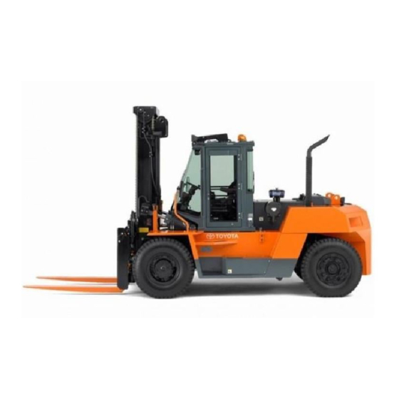
Page 4: Vehicle Exterior Views
VEHICLE EXTERIOR VIEWS HEADGUARD MODEL... - Page 5 CABIN MODEL...
-
Page 6: Vehicle Model
VEHICLE MODEL Payload Vehicle model Standard load center Engine model 10 ton 50-4FD100 11.5 ton 50-4FD115 12 ton 50-4FD120 600 mm J08E-UM (23.6 in) 13.5 ton 50-4FD135 15 ton 50-4FDK150 16 ton 50-4FDK160 FRAME NUMBER Vehicle model Punching format 50-4FD100... -
Page 7: How To Use This Manual
HOW TO USE THIS MANUAL EXPLANATION METHOD 1. Operating procedure Description example • • DISASSEMBLY INSPECTION REASSEMBLY Tightening torque unit m (kgf cm) [ft lbf] → • • • • The numbers may partially be omitted in the illustration. T = 46.1 to 48.1 (470 to 490) [34.0 to 35.4] Disassembly Procedure... -
Page 8: Terminology
2. Matters omitted from this manual This manual omits descriptions of the following jobs, but perform them in actual operation: (1) Cleaning and washing of removed parts as required (2) Visual inspection (partially described) TERMINOLOGY Caution: Important matters, negligence of which may cause accidents. Be sure to observe them. Note: Important matters, negligence of which may cause failures, or matters in operation procedure requiring special attention. -
Page 9: Operating Tips General
(6) Always replace gaskets, packing, O-rings, self-locking nuts and cotterpins with new ones whenever they are disassembled. (7) Use genuine Toyota parts for replacement. (8) Use specified bolts and nuts and observe the specified tightening torque when reassembling. (Tighten to the medium value of the specified tightening torque range.) If no tightening torque is specified, use the value given in the "standard tightening torque table". -
Page 10: Jacking Up
JACKING UP When jacking up the vehicle, always observe the following instructions. • When the fork is loaded, unload it and park the vehicle on a flat surface. Do not park on an inclined or rough ground. • Use a jack with ample capacity and jack up the vehicle at the specified jack-up point. Jacking up at any other point is dangerous. -
Page 11: Hoisting The Vehicle
When the mast ASSY is installed on the vehicle, it is also possible to jack up the front side of the vehicle as follows: Lift the lift bracket to a height not obstructing operation. Place wooden blocks and a plate under the outer mast. Tilt the mast forward to raise the front of the vehicle. -
Page 12: Wire Rope Suspension Angle List
0-10 WIRE ROPE SUSPENSION ANGLE LIST Lifting Com- Suspension Lifting Com- Suspension Tension Tension angle pression method angle pression method 1.00 1.41 1.00 90° 0° 0 time 90° time time time 30° 1.04 0.27 2.00 1.73 30° 120° time time time time 120°... -
Page 13: Safe Load For Each Wire Rope Suspension Angle
(35030) (39510) (40740) Fork length: 1220 mm Attachment A31 Weight increase when the attachment is installed kg (lb) Weight Attachment type 50-4FD100 50-4FD115 50-4FD120 50-4FD135 4FDK150 4FDK160 110 (243) 150 (331) 150 (331) 160 (353) 100 (220) 100 (220) 490 (1080) - Page 14 0-12 Mast weight (including lift bracket and excluding the fork) kg (lb) Mast ASSY weight Lifting height Mast type mm (in) 50-4FD100 50-4FD115 50-4FD120 50-4FD135 4FDK150 4FDK160 2560 2650 2650 2920 3730 3730 3000 (118) (5644) (5842) (5842) (6437) (8223)
- Page 15 0-13 Fork weight kg (lb) Weight (for 2 forks) Fork length mm (in) 50-4FD100 50-4FD115 50-4FD120 50-4FD135 4FDK150 4FDK160 1220 (48.0) (816) (904) (904) (1036) (1036) (1146) 1370 (53.9) (860) (948) (948) (1102) (1102) (1213) 1520 (59.8) (904) (992) (992)
-
Page 16: Electrical Parts Inspection
0-14 ELECTRICAL PARTS INSPECTION 1. Always disconnect the battery plug before inspecting or servicing electrical parts. 2. Pay sufficient attention when handling electronic parts. (1) Never subject electronic parts, such as computers and relays, to impact. (2) Never expose electronic parts to high temperature or moisture. -
Page 17: Bolt & Nut Tightening Torque
0-15 BOLT & NUT TIGHTENING TORQUE Standard bolt & nut tightening torque Tightening torques of standard bolts and nuts are not indicated throughout the manual. Use the charts and table below to judge the standard tightening torque. 1. Judge the tightening torque for the hexagon head bolt, welded bolt or stud bolt having the standard bearing surface according to the tightening torque table by identifying the bolt strength class from the table below. - Page 18 0-16 Identification by part No. Type Part No. Shape Nominal diameter Nominal length Hexagon bolt Nominal diameter Nominal length Class Nominal Nominal length (mm) diameter Stud bolt Nominal diameter Nominal length Class Tightening torque table Standard tightening torque Nominal diameter Pitch Class N•m...
-
Page 19: Hexagon Flange Bolt Tightening Torque
0-17 HEXAGON FLANGE BOLT TIGHTENING TORQUE Nominal diameter Pitch Standard tightening torque Remarks N•m (kgf•cm) [ft•lbf] 7.5 (76.5) [5.5] Built-in washer 12.5 (128) [9.2] 13 (133) [9.6] Built-in washer 31 (316) [22.9] 1.25 30 (306) [22.1] Built-in washer 64 (653) [47.2] 1.25 63 (643) [46.5] Built-in washer... -
Page 20: High Pressure Hose Fitting Tightening Torque
0-18 HIGH PRESSURE HOSE FITTING TIGHTENING TORQUE 1. When connecting a high pressure hose, wipe the hose fitting and corresponding nipple contact surfaces with a clean cloth to remove foreign matter and dirt. Also check that there are no dents or other damage on the contact surfaces before installation. -
Page 21: Recommended Lubricant Quantity & Types
0-19 RECOMMENDED LUBRICANT QUANTITY & TYPES Quantity Applicable portion Russian specification l (US gal) Genuine Toyota diesel oil Apollo diesel oil CD Engine 14.0 (3.7) New special II (5W-30) Engine coolant Genuine Toyota long life Genuine Toyota long life (excluding reservoir 25.0 (6.6) -
Page 22: Lubrication Chart
20. Tilt steering lock device Castle hypoid gear oil W (Russia specification) 7. Brake fluid reservoir tank 21. Brake cooling oil tank C: Genuine Toyota diesel oil new special II (STD) 8. Fuel tank 22. Oil tank Apollo diesel oil CD (5W-30, Russian specification) 9. -
Page 23: Periodic Maintenance
0-21 PERIODIC MAINTENANCE INSPECTION METHOD Inspection, repair or replacement if required M: Measurement, repair or adjustment if required Retightening C: Cleaning L: Lubrication For new vehicle *1: Flaw detector Every Every Every Every Inspection Period 6 weeks 3 months 6 months 12 months Every Every... - Page 24 0-22 Every Every Every Every Inspection Period 6 weeks 3 months 6 months 12 months Every Every Every Every Item 250 hours 500 hours 1000 hours 2000 hours STEERING SYNCHRONIZER ← ← ← Air cleaner clogging ← ← ← Water draining from air tank Compressor hose replacement Air com- Rubber parts replacement...
- Page 25 0-23 Every Every Every Every Inspection Period 6 weeks 3 months 6 months 12 months Every Every Every Every Item 250 hours 500 hours 1000 hours 2000 hours POWER TRANSMISSION SYSTEM Oil leak and oil level ← ← ← ← ←...
- Page 26 0-24 Every Every Every Every Inspection Period 6 weeks 3 months 6 months 12 months Every Every Every Every Item 250 hours 500 hours 1000 hours 2000 hours MATERIAL HANDLING SYSTEM ← ← ← Chain tension ← ← ← Chain anchor bolt abnormality Mast and lift bracket ←...
- Page 27 0-25 Every Every Every Every Inspection Period 6 weeks 3 months 6 months 12 months Every Every Every Every Item 250 hours 500 hours 1000 hours 2000 hours SAFETY DEVICE, ETC. ← ← ← Sounding condition Horn ← ← ← Action ←...
-
Page 28: Periodic Replacement Of Parts And Lubricants
0-26 PERIODIC REPLACEMENT OF PARTS AND LUBRICANTS : Replacement Every Every Every Every 6 weeks 3 months 6 months 12 months Replacement cycle Item Every Every Every Every 250 hours 500 hours 1000 hours 2000 hours Engine oil ← ← ←... - Page 29 ENGINE Page GENERAL ............... 0-3 FEATURES ..............0-4 LUBRICATION SYSTEM ..........0-10 LUBRICATION SYSTEM DIAGRAM ......0-11 COMPONENTS .............. 0-12 FAN BELT ADJUSTMENT PROCEDURE .... 0-25 BLEEDING AIR FROM FUEL SYSTEM ....0-26 ENGINE ASSY ............... 0-27 REMOVAL•INSTALLATION ........... 0-27 RADIATOR ASSY ............
-
Page 30: General
GENERAL Fuel filter Closed ventilator EGR valve Oil level gauge EGR cooler Coolant OUT Air compressor Coolant INl Starter Earthl Supply pump Intake Aiternator Turbocharger Oil filter element Exhaust... -
Page 31: Features
FEATURES Engine mechanical (piston, piston pin and piston ring) Structure Piston and piston pin • The heat-resistant aluminum alloy is used for the piston. The specially shaped combustion chamber is adopted in order to realize excellent combustion and fuel-efficiency. • The outer shape of the piston is optimally profiled with taking a thermal expansion and piston oscillations into account. - Page 32 Engine mechanical (connecting rod and crank shaft) Structure Connecting rod • The connecting rod is made of forged carbon steel. Its large end is horizontally split, which has advantages in rigidity. The bush made of lead bronze with the oil groove in the center is pressed in its small end.
- Page 33 Cam shaft • The camshaft is manufactured by knockdown system. The cam lobe and the com journal are pressed in a hollow carbon steel tube. The cam lobe is welded. • By adopting a special profile for the cam, together with improving inhalation efficiency, quiet operation can be expected.
- Page 34 SYSTEM BLOCK DIAGRAM ACT Relay To each power supply of sensors Battery Main Relay Accelerator signal 1, 2 Diagnosis tool Diagnosis switch Neutral switch Engine rpm sensor Check engine lamp Sub-engine rpm sensor Preheat lamp Glow relay EGR valve 1 drive signal Intake throttle valve drive signal Injector drive signal Supply pump control valve drive signal...
- Page 35 EGR valve • To correspond to the automobile exhaust gas regulations of 2005, the computerized double-seated valve linear solenoid type of EGR valve was adopted. • The computerized double-seated valve linear solenoid type of EGR valve was adopted in order to improve accuracy in adjustment and to reduce particulates and Nox altogether.
- Page 36 Structure • The flame-proof resin that is light and oil resistant is used for the main body of the closed ventilator. For the oil separate part, element-less type, which is maintenance-free, is adopted. • To separate the oil mist in the blowby gas, there is a slewing part for the centrifugation and a filtering part for crash and separation inside.
-
Page 37: Lubrication System
LUBRICATION SYSTEM SPECIFICATION Lubrication method Pressure lubrication by gear pump Oil filters Paper filters for both full flow and bypass Lubricating oil cooler Water cooled multi plate type GENERAL DESCRIPTION • Oil in the oil pan is drawn up through a strainer by the oil pump housed at the rear end of the cylinder block and then lead into the oil cooler where it exchanges heat with cooling water. -
Page 38: Lubrication System Diagram
1-10 LUBRICATION SYSTEM DIAGRAM Roller pin Oil pan Rollar Rocker arm Rocker arm Cross head Adjust screw Valve shaft Cam shaft Cam idle gear shaft Sub idle gear shaft Turbo charger Oil pump Oil filter Oil cooler Main oil hole strainer Connecting Crank shaft... -
Page 39: Components
1-11 COMPONENTS AIR CLEANER Name Quantity AIR CLEANER BRACKET HOSE PIPE, INTAKE HOSE WASHER, PLATE WASHER, SPRING BOLT FLANGE BOLT HOSE CLAMP... - Page 40 1-12 COOLING SYSTEM GENERAL Fan shroud Fan guard Cooling fan Device of fan belt tensioner Intercooler Radiator To engine From engine To torque Fan shroud Radiator From pump converter Intercooler Propeller shaft (For cooling fan drive) From radiator to torque converter oil cooler From toruqe Torque converter oil cooler converter...
- Page 41 1-13 COMPONENT DUCT Name Quantity DUCT, RH DUCT, LH DUCT, UNDER DUCT, UNDER, RH DUCT, UNDER, LH SEAL SEAL SEAL SEAL SPONG SEAL SEAL FRANGE BOLT FRANGE BOLT...
- Page 42 1-14 FAN SUPPORT Name Quantity PULLEY BRACKET, LWR PLATE, FAN PULLEY COVER SUPPORT, FAN HOUSING PULLEY BRACKET, UPR ADJUST BOLT WASHER, PLATE LOCK NUT FRANGE BOLT FRANGE BOLT FRANGE BOLT...
- Page 43 1-15 FAN DRIVEN Name Quantity No. Name Quantity FLANGE BOLT BEARING BOSS SNAP RING OIL SEAL BEARING WASHER, PLATE FAN PULLEY SNAP RING O-RING 1. Apply sealing agent (08833-76002-71) to the entire periphery of the cap. 2. After fitting the cap, apply the caulking to two locations.
- Page 44 1-16 FAN DRIVE Name Quantity OIL SEAL BEARING FAN PULLEY BEARING WASHER, PLATE SNAP RING O-RING PULLEY COVER...
- Page 45 1-17 FAN SHROUD Name Quantity FAN SHROUD, UPR FAN SHROUD, RH FAN SHROUD, LH FAN SHROUD, LWR PULLEY COVER FAN SHROUD, UPR FAN GUARD INSULATOR SPACER BOLT SEAL FLANGE BOLT FLANGE BOLT...
- Page 46 1-18 FAN DRIVE SHAFT FAN SIDE ENGINE SIDE Name Quantity No. Name Quantity WASHER, CD SPRING WASHER, CD SPRING BOLT, SOCKET BOLT, SOCKET PLATE, FLANGE YOKE SET FAN DRIVE SHAFT Bolt No.1 tightening torque 33.6 to 78.4Nm Bolt No.2 tightening torque 30 to 40Nm Apply sealing agent (08833-76002-71) to the screw parts, to both No.1 and No.2.
- Page 47 1-19 INTER COOLER Name Quantity FLANGE, AIR INTAKE FLANGE BOLT HOSE CLAMP HOSE, INTERCOOLER OUTLET, No.2 PIPE, INTERCOOLER OUTLET HOSE, INTERCOOLER OUTLET, No.1 FLANGE TURBO OUTLET WASHER, CD SPRING BOLT, SOCKET HOSE, INTERCOOLER INLET, No.1 PIPE FLANGE BOLT PLATE, RH PLATE, LH FLANGE BOLT SEAL...
- Page 48 1-20 BRAKE COOLING OIL COOLER Name Quantity BRAKE COOLING OIL COOLER HOSE HOSE FITTING CLAMP FLANGE BOLT...
- Page 49 1-21 TORQUE CONVERTER OIL COOLER Name Quantity TORQUE CONVERTER OIL COOLER HOSE, RADIATOR OUTLET HOSE, COOLER OUTLET PIPE HOSE COOLER BRACKET, LH COOLER BRACKET, RH HOSE HOSE FITTING CLAMP FLANGE BOLT FLANGE BOLT CLAMP...
- Page 50 1-22 MUFFLER Details of muffler installation Cover the exhaust port in case of standard specification. A upswept muffler is optional. Name Quantity INSULATOR SPACER PLATE BOLT, FLANGE BRACKET SUB-ASSY, EXHAUST CLAMP, EXHAUST PIPE FLANGE, EXHAUST BOLT, U BOLT, FLANGE NUT, FLANGE BRACKET SUB-ASSY, EXHAUST PIPE BOLT, FLANGE UPSWEPT, EXHAUST...
- Page 51 1-23 ACCELERATOR Name Quantity SENSOR ASSY, ROTARY POSITION GASKET, SENSOR WASHER, PLATE ROLLER, ACCEL LINK BOLT, FLANGE NUT, FLANGE WASHER, PLATE WASHER, PLATE RING, E BUSHING ARM SUB-ASSY, ACCEL ARM SUB-ASSY, SENSOR BOLT, FLAT HEAD SQUARE NECK CUSHION BOLT, FLANGE NUT, FLANGE BRACKET SUB-ASSY, ACCEL ARM COVER SUB-ASSY...
-
Page 52: Fan Belt Adjustment Procedure
1-24 FAN BELT ADJUSTMENT PROCEDURE Tension adjust bolt Bolt No.3 Lock nut No.1 Lock nut No.2 Fan set bolt V belt V-belt tension adjustment standard Brand new parts: 520 ~ 760Nm After using five minutes or longer: 300 ~ 560Nm Adjustment procedure 1. -
Page 53: Bleeding Air From Fuel System
1-25 BLEEDING AIR FROM FUEL SYSTEM Bleeder plug Place a container to receive the discharged fuel under Priming the tip end of the hose connected to the fuel filter. pump Free the priming pump by rotating it counterclockwise. Apply a pressure by operating the priming pump up and down, and bleed air by loosening the bleeder plug. -
Page 54: Engine Assy
1-26 ENGINE ASSY REMOVAL•INSTALLATION 11•12 Removal Procedure Park the vehicle on a flat ground and chock the wheels. Remove the cabin or head guard. (See P.8-30.) Disconnect the battery terminal. Disconnect the radiator hose. (See P.1-27.) Remove the propeller shaft for cooling. Disconnect the fuel piping and wiring from the engine. -
Page 55: Removal•Installation
1-27 Installation Procedure The installation procedure is the reverse of the removal procedure. Note: • After installation, bleed air from the fuel system. • Prepare an oil receiver since the hydraulic oil will run out when the piping is disconnected. Caution: At the time of maintenance, inspection, adjustment or replacement of the torque converter ASSY, remove the parking brake air chamber before disconnecting the battery... - Page 56 Thank you very much for your reading. Please Click Here Then More Information.
Need help?
Do you have a question about the 50-4FDK160 and is the answer not in the manual?
Questions and answers