Table of Contents
Advertisement
Created according to regulations applicable in Germany.
For operation in industrial environments only!
Type
ERCH/ERKH
Schniewindt GmbH & Co. KG
Schöntaler Weg 46
58809 Neuenrade, Germany
Tel.: +49 2392 692-0
Fax.: +49 2392 692-11
info@schniewindt.de
www.schniewindt.de
Translation
Operation Manual
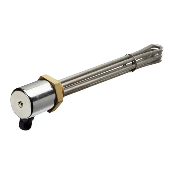
Screw-in Heater
: ERCH/ERCT/ERCB/ERCTB/ERCU
ERKH/ERKT/ERKB/ERKTB/ERKU
ERCT/ERKT
ERCB/ERKB
ERCTB/ERKTB
Page 1 of 17
Created on 23.07.2020
en
Advertisement
Table of Contents

Related Manuals for Schniewindt ERCTB


Summary of Contents for Schniewindt ERCTB
- Page 1 Operation Manual Screw-in Heater Type : ERCH/ERCT/ERCB/ERCTB/ERCU ERKH/ERKT/ERKB/ERKTB/ERKU ERCH/ERKH ERCT/ERKT ERCTB/ERKTB ERCB/ERKB Schniewindt GmbH & Co. KG Schöntaler Weg 46 58809 Neuenrade, Germany Tel.: +49 2392 692-0 Fax.: +49 2392 692-11 info@schniewindt.de www.schniewindt.de Page 1 of 17 Created on 23.07.2020...
-
Page 2: Table Of Contents
Product specifications ................5 Mounting instructions ................6 Mounting ....................6 Installation general ................. 7 8.1. Installation ERCH / ERKH ..............8 8.2. Installation of units with rotatable element ..........9 8.3. Installation of units with a red hood ............10 Commissioning .................. -
Page 3: Intended Use
Intended use Intended use The unit is used for heating liquid or gaseous media. The medium, the operating conditions and the installation position are tailored to the respective application and listed in the order confirmation. The unit is used for heating the medium specified in the order confirmation. The operating conditions of the order confirmation must be observed. -
Page 4: Identify Unit
Identify unit Identify unit Type designation Production number (Please specify when making inquiries) Type code (see point ) Installation length in cm Output in kW Type code ER***/**-** Output in kW Installation length in cm No temperature monitoring H = Hood With temperature monitoring: T = Thermostat controller L = Limiter... -
Page 5: Product Specifications
Product specifications Product specifications Name : Screw-in heater For technical details see order confirmation. Note: Cable gland temperature range : -20°C (dynamic) to +100°C. -40°C (static, briefly) The cable glands can be used at temperatures of between -20°C and -40°C only if static stress is present at the place of use. -
Page 6: Mounting Instructions
Mounting instructions Mounting instructions During operation, the minimum or maximum ambient temperatures at the connection hood specified in these instructions must not be exceeded or fallen short of. If the ambient temperature is different, the unit must be switched off (e.g. a suitable room temperature controller or similar unit should be provided). -
Page 7: Installation General
Installation general Installation general The activities described below are reserved for qualified electricians. The provisions of the DIN VDE 0100 (low voltage systems) and DIN VDE 0298-4 (high-voltage systems) or the locally applicable regulations must be observed when planning projects, selecting and installing the electrical system. -
Page 8: Installation Erch / Erkh
Installation ERCH / ERKH 8.1. Installation ERCH / ERKH The position of the cable gland can be adapted. To do this, loosen the sleeve nut in the hood. However, the hood may only be rotated a maximum of 45° to the right or left. -
Page 9: Installation Of Units With Rotatable Element
Installation of units with rotatable element 8.2. Installation of units with rotatable element The position of the cable bushing can be adapted. To do this, loosen the threaded pins, but do not unscrew them completely. However, the connection head may only be rotated a maximum of 45° to the right or left. -
Page 10: Installation Of Units With A Red Hood
Installation of units with a red hood 8.3. Installation of units with a red hood 1. Unscrew the cover of the connection head. 2. Make sure that the earthing cable has not become detached. Max. tensile load of the earthing cable 10 N. 3. -
Page 11: Controller Setting
Controller setting Controller setting The medium temperature is set by the integrated temperature controller. The integrated controller is set to the desired temperature by turning the scale lever. The setting range of the scale lever can be found on the attached scale or in your order confirmation. ERCT / ERKT Page 11 of 17 Created on 23.07.2020... -
Page 12: Limiter Setting
Limiter setting Limiter setting The integrated temperature limiter (TL) protects both the medium and the unit from excessive temperatures. The TL is set to the smallest value at the factory. Caution: The limiter setting takes place under voltage. DANGER Lethal danger from electric current Death/serious bodily injuries/material damage The TL can be set as follows: Set the limiter to maximum. -
Page 13: Units With Limiter, Internal Setting Ercb / Erkb
Units with limiter, internal setting ERCB / ERKB Units with limiter, internal setting ERCB / ERKB ERCB / ERKB Page 13 of 17 Created on 23.07.2020... -
Page 14: Units With Controller And Limiter Erctb / Erktb
Units with controller and limiter ERCTB / ERKTB Units with controller and limiter ERCTB / ERKTB Figure 1 Figure 2 Figure 3 Figure 1: The 3-pin regulator/limiter combination is available in two versions: Limiter set permanently to 92°C, controller adjustable within the range from 30°C to 78°C Limiter set permanently to 100°C, controller adjustable within the range from 30°C to 85°C Figure 2: Regulator with external setting, limiter with internal setting. -
Page 15: Units With Dry-Running Protection Ercu / Erku
Units with dry-running protection ERCU / ERKU Units with dry-running protection ERCU / ERKU Intended use: Units with dry-running protection are used to heat water in containers and storage tanks with strongly fluctuating filling levels. Operating conditions: max. 100°C at max. 10 bar Other operating conditions are only permissible if they are in your order confirmation. -
Page 16: Remedying Malfunctions
Remedying malfunctions Remedying malfunctions The activities described below are reserved for qualified electricians. Malfunction: Unit does not warm up Remedy: - Check fuses - Check connection voltage Switch off the system and secure it to prevent unintentional restart. Open the connection head and inspect the heating insert for electrical continuity. -
Page 17: Dismantling
Dismantling Dismantling Switch off the system and secure it to prevent unintentional restart. Allow the unit to cool down to room temperature. Disconnect connection cable and remove. The system must be depressurised. Drain the medium beforehand and dispose of accordingly. Storage The storage room must be dry and dust-free.
Need help?
Do you have a question about the ERCTB and is the answer not in the manual?
Questions and answers