Table of Contents
Advertisement
Created according to regulations applicable in Germany.
For operation in industrial environments only!
Type
ERCH/ERKH
Schniewindt GmbH & Co. KG
Schöntaler Weg 46
58809 Neuenrade, Germany
Tel.: +49 2392 692-0
Fax.: +49 2392 692-11
info@schniewindt.de
www.schniewindt.de
Translation
Operation Manual
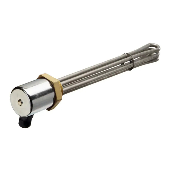
Screw-in Heater
: ERCH/ERCT/ERCB/ERCTB/ERCU
ERKH/ERKT/ERKB/ERKTB/ERKU
ERCT/ERKT
ERCB/ERKB
ERCTB/ERKTB
Page 1 of 17
Created on 23.07.2020
en
Advertisement
Table of Contents

Related Manuals for Schniewindt ERCT


Summarization of Contents
Intended Use
Application and Media
The unit heats liquid or gaseous media. Application and conditions are specified in the order confirmation.
General Safety Instructions
Operational Safety Guidelines
Read and understand the manual before use. Do not modify the unit; this invalidates conformity and can cause injury.
Identifying the Unit
Unit Identification Plate
Details on the identification plate: Type designation, S/N, Voltage, Power, Protection Class, Year of Manufacture.
Type Code Explanation
Decoding the Type Code
Explanation of type code components: output, installation length, temperature monitoring, material, and type series.
Product Specifications
Cable Gland Temperature Limits
Temperature range for cable glands: -20°C (dynamic) to +100°C, -40°C (static, briefly). Static stress conditions apply.
Importance of Temperature Recording
Units require temperature recording. Install a suitable controller/limiter if not manufacturer-installed. Refer to order confirmation.
Mounting Instructions
Ambient Temperature and Insulation
Respect ambient temperature limits for the connection hood. Connection head must not be insulated. Max 80°C in connection area.
Preventing Overheating with Medium
Unit must be covered by heated medium. Use level/flow monitors; ensure adequate medium coverage (min. 50 mm).
Mounting Procedures
Installation Best Practices
Use correct tools and seals. Ensure thread condition. Screw in firmly, retighten after first heating if necessary.
General Installation Guidelines
Qualified Electrician Requirement
Installation activities are for qualified electricians only. Follow VDE and local regulations for electrical connections.
Installation ERCH / ERKH
Cable Gland and Hood Adjustment
Adapt cable gland position by loosening sleeve nut. Hood rotation is limited to a maximum of 45°.
Earthing Cable Handling
Ensure the earthing cable is not detached. Maximum tensile load for the earthing cable is 10 N.
Cable Gland Installation
Insert cables, tighten cap nut by hand, then with specified torque for strain relief and protection class.
Wiring and Earthing Connection
Connect cable per wiring diagram. Provide earthing with an open cable lug on the threaded flange.
Installation of Units with Rotatable Element
Rotatable Element Positioning
Adapt cable bushing position by loosening threaded pins. Connection head rotation is limited to 45°.
Earthing Cable Safety
Ensure the earthing cable is securely attached. Max tensile load is 10 N.
Cable Gland Tightening
Tighten cable gland nut to ensure strain relief and protection class. Ensure cable/connection compatibility.
Connection and Earthing Procedure
Connect cable per wiring diagram. Provide earthing via cable lug on threaded flange.
Final Assembly Steps
Attach hood securely with screws. Re-attach scale lever for units with external adjustment.
Installation of Units with Red Hood
Cover Removal and Earthing Check
Unscrew connection head cover and verify the earthing cable is still attached.
Earthing Cable Load Limit
The earthing cable has a maximum tensile load of 10 N. Ensure it is not detached.
Cable Gland Nut Tightening
Tighten the cable gland nut to ensure strain relief and protection class. Compatibility is crucial.
Cable Connection and Grounding
Follow wiring diagram for connection. Ground the unit using a cable lug on the threaded flange.
Commissioning Procedures
Pre-Operation Checks
Verify connections, medium coverage of heated length, and proper connection of temperature limiter.
Setting the Temperature Controller
Set the controller to the desired temperature. Ensure the connection head is sealed correctly after adjustment.
Controller Setting
Adjusting the Integrated Controller
Set medium temperature by turning the scale lever on the integrated controller. Refer to scale or order confirmation.
Limiter Setting and Reset
Integrated Temperature Limiter (TL)
The TL protects against excessive temperatures, factory-set to the minimum value. Setting must be done under voltage.
Procedure for Setting the TL
Set TL to max, heat unit, turn spindle left to define trigger temp, set limiter temp 20-30°C higher.
Limiter Reset Procedure
How to Reset a Triggered Limiter
Open connection hood, press restart button to unlock the TL. Ensure system is secured before resetting.
Units with Internal Limiter (ERCB / ERKB)
Identifying the Reset Button
Visual guide to the 'RESET' button on ERCB/ERKB units with internal limiter settings.
Units with Controller and Limiter (ERCTB / ERKTB)
3-Pin Regulator/Limiter Versions
Describes two versions: fixed limiter (92/100°C) with adjustable controller (30-78°C / 30-85°C).
External Regulator, Internal Limiter
Configuration with external setting for regulator and internal setting for limiter. Details on diagrams/order confirmation.
Internal Regulator and Limiter
Configuration with internal settings for both regulator and limiter. Details on diagrams/order confirmation.
Units with Dry-Running Protection (ERCU / ERKU)
Application and Operating Limits
Heats water in tanks with fluctuating levels. Max. 100°C at 10 bar. Protects unit from burnout.
Mounting Dry-Running Protection Units
Screw horizontally into G1 ½" thread. Dry-running protection sensor must be at the highest point.
Repairs and Maintenance
Repair Guidelines
Contact manufacturer for repairs. Use only approved parts and trained personnel. Improper repairs are dangerous.
Troubleshooting Malfunctions
Unit Not Warming Up
Check fuses and voltage. Inspect heating insert continuity; replace if necessary. Contact manufacturer for replacement.
Preventive Maintenance
Annual Inspection Schedule
Visually inspect unit annually. Measure insulation/resistance, test controls, check for damage/deposits/leaks.
Heating Element Care
Clean heating elements carefully to remove deposits. Perform annual safety device function inspection.
Dismantling Procedures
Safe Unit Dismantling Steps
Switch off, cool down, disconnect, depressurise, and drain medium before disposal.
Storage Recommendations
Optimal Storage Conditions
Store in dry, dust-free environment (-40°C to +40°C). Seal openings and use drying agent in terminal compartment.
Insulation Resistance Check for Storage
Ensure insulation resistance > 2 MΩ before operation after prolonged storage. Measure with 500V DC.
Disposal Instructions
Environmentally Responsible Disposal
Remove deposits and dispose of unit according to local regulations. Separate materials for recycling.
Need help?
Do you have a question about the ERCT and is the answer not in the manual?
Questions and answers