Advertisement
Quick Links
19238-6NL-04
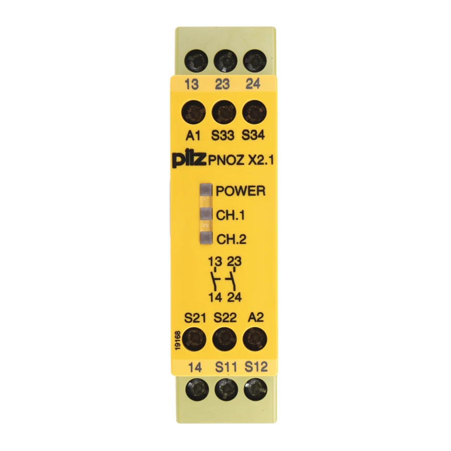
PNOZ X2, PNOZ X2.1, PNOZ X2.2
Sicherheitsbestimmungen
• Das Gerät darf nur von Personen
installiert und in Betrieb genommen
werden, die mit dieser Betriebsanleitung
und den geltenden Vorschriften über
Arbeitssicherheit und Unfallverhütung
vertraut sind. Beachten Sie die VDE-
sowie die örtlichen Vorschriften, insbe-
sondere hinsichtlich Schutzmaßnahmen.
• Beim Transport, der Lagerung und im
Betrieb die Bedingungen nach EN 60068-
2-6 einhalten (s. technische Daten).
• Durch Öffnen des Gehäuses oder eigen-
mächtige Umbauten erlischt jegliche Ge-
währleistung.
• Montieren Sie das Gerät in einen
Schaltschrank; Staub und Feuchtigkeit
können sonst zu Beeinträchtigungen der
Funktionen führen.
• Sorgen Sie an allen Ausgangskontakten
bei kapazitiven und induktiven Lasten für
eine ausreichende Schutzbeschaltung.
Bestimmungsgemäße Verwen-
dung
Das Sicherheitsschaltgerät dient dem
sicherheitsgerichteten Unterbrechen eines
Sicherheitsstromkreises.
Das Sicherheitsschaltgerät erfüllt Forderun-
gen der EN 60947-5-1, EN 60204-1 und
VDE 0113-1 und darf eingesetzt werden in
Anwendungen mit
• Not-Halt-Tastern
• Schutztüren
Das Gerät ist nicht für die Absicherung von
berührungslosen Verdeckungen geeignet, da
kein dynamischer Start möglich ist.
Gerätebeschreibung
Das Sicherheitsschaltgerät PNOZ X2/X2.1/
X2.2 ist in einem S-95-Gehäuse unterge-
bracht. Es kann mit 24 V Wechselspannung
oder mit 24 V Gleichspannung betrieben
werden.
Merkmale:
• Relaisausgänge: 2 Sicherheitskontakte
(Schließer), zwangsgeführt
• Anschlussmöglichkeit für Not-Halt-
Taster, Schutztürgrenztaster und
Starttaster
• PNOZ X2: überwachter Starttaster
• PNOZ X2.1: automatischer Start möglich
• PNOZ X2.2: wie PNOZ X2, zusätzlich
können mehrere Geräte parallel mit einem
Starttaster gestartet werden
• Statusanzeige
• Überwachung externer Schütze möglich
• keine galvanische Trennung
Das Schaltgerät erfüllt folgende Sicherheits-
anforderungen:
• Schaltung ist redundant mit Selbst-
überwachung aufgebaut
Safety Regulations
• The unit may only be installed and
operated by personnel who are familiar
with both these instructions and the
current regulations for safety at work and
accident prevention. Follow VDE and
local regulations especially as regards
preventative measures.
• Transport, storage and operating
conditions should all conform to
EN 60068-2-6.
• Any guarantee is void following opening of
the housing or unauthorised
modifications.
• The unit should be panel mounted,
otherwise dampness or dust could lead to
function impairment.
• Adequate protection must be provided on
all output contacts especially with
capacitive and inductive loads.
Authorised Applications
The safety relay provides a safety-related
interruption of a safety circuit.
The safety relay meets the requirements of
EN 60947-5-1, EN 60204-1 and VDE 0113-
1 and may be used in applications with
• E-STOP pushbuttons
• Safety gates
The device is not suitable for non-contact
barriers (e.g. light curtains) because a
dynamic start is not possible.
Description
The Safety Relay PNOZ X2/X2.1/X2.2 is
enclosed in a S-95 housing. Every unit can
be operated with 24 V AC or 24 V DC.
Features:
• Relay outputs: 2 safety contacts (N/O),
positive-guided.
• Connections for Emergency Stop Button,
Safety Gate Limit Switch and Reset
button.
• PNOZ X2: monitored manual reset
• PNOZ X2.1: automatic reset possible
• PNOZ X2.2: As PNOZ X2. In addition,
several units may be started in parallel
using one start button.
• Status Indicators.
• Feedback Control Loop for monitoring of
external contactors/relays possible
• no galvanic seperation
The relay complies with the following safety
requirements:
• The circuit is redundant with built-in self-
monitoring
- 1 -
Conseils préliminaires
• La mise en oeuvre de l'appareil doit être
effectuée par une personne spécialisée
en installations électriques, en tenant
compte des prescriptions des différentes
normes applicables (NF, EN, VDE...)
notamment au niveau des risques
encourus en cas de défaillance de
l'équipement électrique.
• Respecter les exigences de la norme
EN 60068-2-6 lors du transport, du
stockage et de l'utilisation de l'appareil.
• L'ouverture de l'appareil ou sa modifi-
cation annule automatiquement la
garantie.
• L'appareil doit être monté dans une ar-
moire; l'humidité et la poussière pouvant
entraîner des aléas de fonctionnement.
• Vérifiez que le pouvoir de coupure des
contacts de sortie est suffisant en cas de
circuits capacitifs ou inductifs.
Domaines d'utilisation
Le bloc logique de sécurité sert à
interrompre en toute sécurité un circuit de
sécurité.
Le bloc logique de sécurité satisfait aux
exigences des normes EN 60947-5-1,
EN 60204-1 et VDE 0113-1 et peut être
utilisé dans des applications avec des
• poussoirs d'arrêt d'urgence
• protecteurs mobiles
L'appareil n'est pas adapté à la surveillance
de barrières immatérielles car une validation
dynamique n'est pas possible (surveillance
du circuit de réarmement).
Description de l'appareil
Inséré dans un boîtier S 95, le bloc logique
de sécurité PNOZ X2/X2.1/X2.2 peut être
alimenté en 24 V AC ou en 24 V DC.
Particularités :
• Sorties disponibles : 2 contacts à
fermeture de sécurité
• Bornes de raccordement pour poussoirs
AU, détecteurs de position et poussoir de
validation
• PNOZ X2: surveillance du circuit de
validation
• PNOZ X2.1: réarmement automatique
possible
• PNOZ X2.2: comme PNOZ X2, mais
permet le réarmement de plusieurs
appareils en parallèle avec un seul
poussoir de réarmement.
• LEDs de visualisation
• Auto-contrôle des contacteurs externes
possible
• pas d'isolation galvanique
Le relais PNOZ X2/X2.1/X2.2 répond aux
exigences suivantes :
• conception redondante avec auto-
surveillance
Advertisement

Related Manuals for Pilz 774 303


Summarization of Contents
Safety Regulations
General Safety Provisions
Essential rules for installation, operation, and handling of the safety relay.
Transport, Storage, and Operating Conditions
Compliance with EN 60068-2-6 for transport, storage, and operation.
Installation and Modification
Warning against opening housing or unauthorized modifications voids warranty.
Authorised Applications
Safety Circuit Interruption
The safety relay provides safety-related interruption of a safety circuit.
Suitable Applications
Use in applications with E-STOP pushbuttons and safety gates.
Unsuitable Applications
Not suitable for non-contact barriers due to dynamic start requirement.
Device Description
Housing and Power Options
The safety relay is housed in an S-95 unit and operates on 24 V AC or 24 V DC.
Product Features
Includes relay outputs, connection options for E-STOP/gate switches, status indicators.
Safety Compliance
Relay complies with safety requirements for redundancy and self-monitoring.
Function Description
Initialisation and Ready State
Unit is ready when POWER LED is illuminated and reset circuit is closed.
Input Circuit Closed
Relays energise, status indicators illuminate, safety contacts close.
Input Circuit Opened
Relays de-energise, status indicators extinguish, safety contacts open.
Operating Modes
Single-channel Operation
Input wiring without redundancy, earth faults detected in reset circuit.
Two-channel Operation
Redundant input circuit detects earth faults and shorts across buttons.
Automatic Reset
Unit becomes active as soon as the input circuit is closed.
Manual Reset
Unit is active only after a reset button is pressed or reset contact is closed.
Monitored Manual Reset
Voltage must be applied before start/reset contacts close for safety.
Installation
Mounting Requirements
Unit must be panel mounted with minimum IP54 protection.
DIN-Rail Attachment
Unit can be attached to a DIN-rail using its rear notch.
Operation
Contact Protection
Fuse recommended for output contacts to prevent welding.
Max. Cable Length Calculation
Formula and details for calculating maximum input circuit cable length.
Short-Circuit Detection Test
Procedure to test the short-circuit detection function after installation.
Wiring Guidelines
Recommendations for wiring material and proximity switches.
Application Examples
Input Circuit Wiring
Examples for single-channel and two-channel input circuits.
Safety Gate Control
Example for dual-channel safety gate control wiring.
External Contactor Wiring
Example for expanding contacts using external contactors.
Troubleshooting
Earth Faults
Behavior and recovery procedure for earth faults.
Contact Failure
Issues with welded contacts and reactivation troubleshooting.
Power LED Issues
Reasons for the Power LED not illuminating (short-circuit, no power).
Technical Data
Electrical Data
Supply voltage, power consumption, frequency range, residual ripple.
Safety Contact Ratings
Details on instantaneous safety contacts and utilization category.
Cable and Fuse Specifications
Contact material, fuse characteristics, and max. cable resistance.
Timing Specifications
Switch-on Delay
Delay before the unit becomes active.
Reset Times
Delay times for de-energisation and monitored start.
Environmental Conditions
EMC Compliance
Electromagnetic compatibility according to standards.
Vibration and Climate
Suitability for vibration and climatic conditions.
Mechanical Specifications
Housing and Terminals
Details on housing material and terminal area.
Cable Cross-Section and Torque
Specification for conductor cross-section and connection terminal torque.
Order Information
Product Variants and Part Numbers
Table listing product types, features, terminals, and order numbers.
Output Relay Service Life
Service Life Graph
Graph showing service life based on switching cycles and current.
Declaration of Conformity
Machinery Directive Compliance
Product compliance with the Machinery Directive 2006/42/EC.
Need help?
Do you have a question about the 774 303 and is the answer not in the manual?
Questions and answers