
Related Manuals for Armstrong Flo-Direct 2.0 AFD-3000


Summarization of Contents
Safety
Icon Legend
Explains safety icons like Danger, Warning, Caution, and Burn Hazard for user safety.
General Safety Guidelines
Provides essential safety practices for installation, maintenance, and operation of the equipment.
Warnings and Cautions
Highlights risks such as fire, explosion, and scald burns, along with general precautions.
The Flo-Direct® System
Typical System
Illustrates the basic components: Heater, Transfer Pump, and Storage Tank.
Specifications
Heater
Details materials of construction for the heater components.
Operational Specifications
Lists operational parameters like pressure, temperature, and efficiency.
Technical Specifications
Mentions UL standard compliance and power requirements.
Dimensions
Flo-Direct® Dimensions and Weights
Provides model dimensions, connections, weight, and BTU/hr rating.
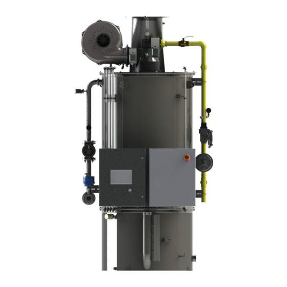
Orientation
Top Plate
Identifies components on the top plate of the heater.
Upper Canister
Labels parts within the upper section of the heater.
Lower Canister
Identifies components located in the lower section of the heater.
Transfer Pump Assembly
Materials of Construction
Lists the materials used for the transfer pump components.
Dimensions and Operational Specifications
Provides model specs, flow rates, connections, and power for transfer pumps.
Storage Tank
Materials of Construction
Details the construction materials of the storage tank.
General Specifications
Outlines design standards, pressure, temperature, and seismic codes for the tank.
Orientation
Storage Tank Orientation
Illustrates and labels various ports and features on the storage tank.
Assembly and Installation
Unpacking
Provides instructions and considerations for unpacking the heater.
Installing Large Heaters
Details steps for setting up and connecting larger heater units.
Installing Small Heaters
Outlines the procedure for installing smaller heater models.
Installing Exhaust Ducting
Guides on connecting and supporting the exhaust ducting system.
Installing Intake Air Ducting
Provides instructions for installing the intake air ducting.
Electrical Panels
Control Panel
Identifies components within the main control panel.
Disconnect Panel
Details the components within the disconnect panel.
Heater Label
Shows a sample label with essential heater specifications.
Electrical Connections
Top Plate to Upper Canister
Illustrates wiring steps between the top plate and upper canister.
Upper to Lower Canister
Details wiring connections between the upper and lower canister sections.
Transfer Pump
Outlines wiring steps for connecting the transfer pump.
Storage Tank
Describes installing float switches and wiring for the storage tank.
Main Power Connection
Provides instructions for connecting the main power supply to the unit.
Operation
Description of Operation
Explains the thermal exchange process and component functions.
Sequence of Operation
Details the step-by-step process of the heater's start-up and shutdown.
Pre-Start-Up Checklist
A comprehensive checklist for installers before initial operation.
Commissioning
Inspecting Installation
Verifies that all installation steps and connections are correctly performed.
Inspecting Water System
Checks water connections, pressure, flow, and for leaks.
Turn on fuel
Details procedures for turning on fuel, checking gas pressure, and safety features.
Periodic Maintenance
Maintenance Schedule
Provides a schedule of daily, weekly, monthly, and annual maintenance tasks.
High Temperature Switch Check
Step-by-step guide to check the functionality of the high temperature switch.
Troubleshooting
Troubleshooting Table
Lists common problems, probable causes, and corrective actions.
PLC I/Os
Details PLC inputs, outputs, and drive commands for advanced troubleshooting.
Parts Lists
Top Plate
Identifies components and part numbers for the top plate assembly.
Water Train
Lists part numbers for components in the water train.
Control Panel
Lists part numbers for components within the control panel.
Disconnect Panel
Lists part numbers for components in the disconnect panel.
Fuel Train
Identifies components and part numbers for the fuel train.
Lower Canister
Lists part numbers for components of the lower canister.
Storage Tank
Lists part numbers for components of the storage tank.
Appendix: HMI Interface
Main Screen
Describes the default HMI screen showing heater status and basic controls.
Manual Run Control
Explains how to use START/STOP buttons for manual operation.
Run Mode
Describes the MANUAL and AUTO modes for heater operation.
Setpoint and Mode
Details how to adjust setpoints and select operating modes (Modulating/Positioning).
Menu
Explains that the menu button navigates to other HMI screens.
Menu Screen
Shows the main navigation screen for accessing various HMI functions.
I/O List
Displays PLC inputs, outputs, and VFD commands with status indicators.
Trending Screen
Records and displays a 10-minute trend of setpoint, outlet temp, and burner position.
Alarms
Tracks active and non-active alarms, with reset procedures and fault code references.
Transfer Pump
Allows adjustment of VFD speeds and displays transfer pump status.
Need help?
Do you have a question about the Flo-Direct 2.0 AFD-3000 and is the answer not in the manual?
Questions and answers