Table of Contents
Advertisement
Bulletin No. AY-780-K
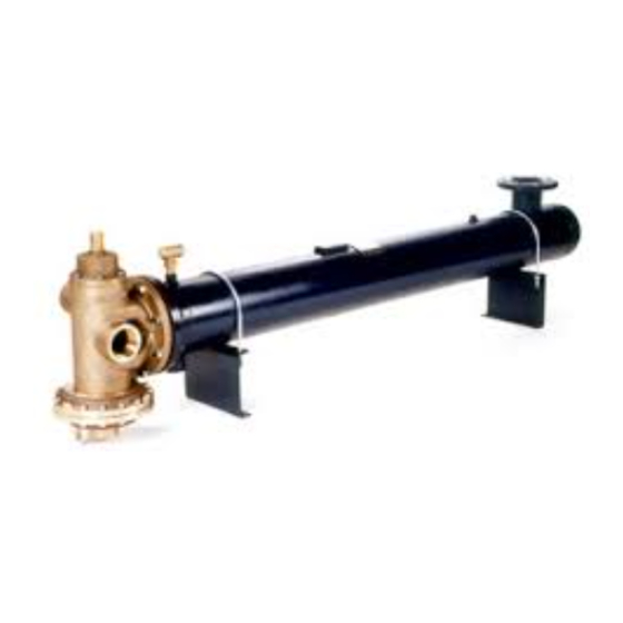
FOR SINGLE AND DOUBLE WALL UNITS
This bulletin should be used by experienced personnel as a guide to the installation of the
FLO-RITE-TEMP Instantaneous Water heater. Selection or installation of equipment should always
be accompanied by competent technical assistance. You are encouraged to contact Armstrong
International, Inc. or its local sales representative for additional information.
Advertisement
Table of Contents

Subscribe to Our Youtube Channel
Related Manuals for Armstrong FLO-RITE-TEMP


Summary of Contents for Armstrong FLO-RITE-TEMP
- Page 1 FOR SINGLE AND DOUBLE WALL UNITS This bulletin should be used by experienced personnel as a guide to the installation of the FLO-RITE-TEMP Instantaneous Water heater. Selection or installation of equipment should always be accompanied by competent technical assistance. You are encouraged to contact Armstrong...
- Page 2 If 2-15 psig of steam is available a pressure reducing valve is NOT required. If a pressure reducing valve is required, an Armstrong Inverted Bucket Steam Trap is recommended to drain condensate at the inlet of the pressure reducing valve.
-
Page 3: Water Piping Installation
Fig. 3-1 An 18 inch minimum thermal loop should be piped into the water inlet and outlet of the FLO-RITE-TEMP and should be located as close to the mixing valve as possible (See Fig. 3-1A). These loops will act as a thermal check valve or heat trap to prevent the conduction of heat through the water from the unit during inactive times. - Page 4 Option #1 A temperature relief valve set at roughly 15-30 degrees above that of the FLO-RITE-TEMP will help prevent any chance of overheated water reaching the faucets. (NOTE: Normally unit will fail closed and either no water or only cold water will flow from the unit.)
- Page 5 Model GP-2000W1P system, when piped as shown in the Option 4 drawing, will provide a safe dependable shut down of the main steam valve when the water pressure fails or drops rapidly on the Flo-Rite-Temp. Unlike a solenoid application, which shuts the steam down when the water pressure drops below a pre-set point, the GP-2000W1P offers another benefit that it allows the system to keep producing hot water even when the water pressure is below the set pressure.
-
Page 6: Shutdown Procedures
Turning clockwise raises the discharge piping going from the diverting valve back to the temperature and counter-clockwise lowers the inlet of the FLO-RITE-TEMP is closed (this is discharge temperature. Make the appropriate the isolation valve downstream of port “B” of the adjustment to achieve the desired set point. - Page 7 example if a set point of 140 °F is desired and the START-UP AND ADJUSTING PROCEDURE temperature reading is 155 °F, you must turn the FOR MODEL 535EP, 665SEP and 8120 low flow adjustment counter-clockwise to lower the set point temperature from 155 °F down to 140 °F.
- Page 8 With the unit now isolated from the hot water the unit has been cleaned. Never attempt to system and all flow of water being directed to re-adjust the unit with a dirty tube bundle - drain, slowly increase the water demand to always clean tube bundle first.
- Page 9 20 degrees below the close to the point of water use eliminating the need for set point of the FLO-RITE-TEMP and will maintain a recirculation system. the temperature in the loop between the set point of...
- Page 10 Providing accurate hot water temperature control. turn the pump on. Water flows out of the bottom of the tank to the inlet of the FLO-RITE-TEMP. The Providing a back up alternative during tank water continues this cycle until the aquastat in the maintenance.
- Page 11 Incoming cold water is heated between 120 to Because there is no storage tank, there is no danger 130 degrees F by the Flo-Rite-Temp. (The unit is set of legionella forming in the stored warm water. All water is heated instantaneously on the spot, there is no shortage of heated water or shower time limits.
- Page 12 Single Wall and Double Wall Profile Model 415 and 535 Profile Shown (665 and 8120 valve shows that connections for water inlet and outlet are on opposite sides of the valve body). Fig. 12-1 Table 12-1. Dimensions & Weights Dimensions Connections Model 4-1/2...
- Page 13 FLO-RITE-TEMP Table 13-1 CAPACITIES AND STEAM LOADS Standard Standard Hot Water Capacities* Steam Capacities Hot Water Capacities* Steam Capacities Inlet Inlet Steam Pressure Steam Pressure Steam Pressure Steam Pressure Temp. Temp. Temp. Temp. Model psig psig psig psig psig psig psig psig °F...
- Page 14 Decrease steam pressure (2 - 15 psig). Extreme hot water Recirculated water is continually diverting Check diverting valve for a stuck or failed thermal comes out of the through the Flo-Rite-Temp. capsule. unit. The steam is superheated. Pipe to saturated steam.
- Page 15 NOTE: NOTE: parallel. Single wall installation shown - Double wall would be similar. See your Armstrong Representative for Single wall installation shown - Double wall would be similar. See your Armstrong Representative for Single wall installation shown - Double wall would be similar. See your Armstrong Representative for Single wall installation shown - Double wall would be similar.
- Page 16 FLO-RITE-TEMP internally. Armstrong-Yoshitake, Inc. 221 Armstrong Blvd., P.O. Box 408, Three Rivers, Michigan 49093 - USA Ph: (616) 279-3600 Fax: (616) 273-8656 Steam Traps \ Humidifiers \ Steam Coils \ Valves \ Air Vents \ Pumping Traps \ Water Heaters Bulletin No.
Need help?
Do you have a question about the FLO-RITE-TEMP and is the answer not in the manual?
Questions and answers