
Related Manuals for Armstrong Digital-Flo DFS1540


Summary of Contents for Armstrong Digital-Flo DFS1540
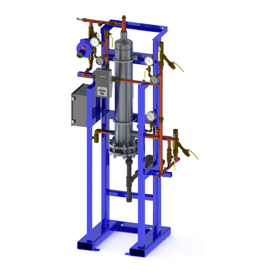
- Page 1 Digital-Flo Semi-Instantaneous ® Steam-to-Water, Shell and Tube, Water Heater Installation Operation & Maintenance Manual Please read and save these instructions. 789-EN...
-
Page 2: Table Of Contents
Table of Contents Safety ................3 General Description ............4 Typical Piping Layout ............5 Specifications ..............6-8 Dimensions ..............9 Precautions ..............10 Installation Requirements ........... 11-16 Commissioning..............17-18 Safety Shutoff Valve ............19 Periodic Maintenance ............20-23 Preventative Maintenance and Fitting Spare Parts ...... 24 Troubleshooting ............... -
Page 3: Safety
Safety Icon Legend — DANGER! … Injury or death and property damage are imminent — WARNING! … Injury or death and property damage are possible — CAUTION! … Potential property damage, expensive repairs, and/or voiding the equipment warranty may result BURN HAZARD! Contact with steam, hot water, or hot metal surfaces can cause severe skin burns. -
Page 4: General Description
1. Because the DFSI is customizable, there may be optional components that are not addressed in this installation and operation manual (IOM). 2. Armstrong reserves the right to make design or specification changes without notification. 3. Refer to IOM-501 for The Brain –... -
Page 5: Typical Piping Layout
Typical Piping Layout Designs, materials, weights and performance ratings are approximate and subject to change without notice. Visit armstronginternational.com for up-to-date information. -
Page 6: Specifications
Specifications Technical Specifications Operating Specifications Steam Supply Pressure 2-15 PSIG (0.14-1 barg) Water Supply Pressure 20-150 PSIG (1.4-10 barg) Minimum Inlet Supply Water Temperature 34°F (1°C) Set Point Range (DRV) 81-158°F (27-70°C) Minimum System Recirculation Flow 10 GPM (38 LPM) for DRV80 or 50 / 5 GPM (19 LPM) for DRV40 Minimum System Draw Off 0 GPM / LPM Minimum Distance to First Outlet... - Page 7 Specifications - continued Double-Wall, Heat Exchanger Component Material Heat Exchanger Shell 316 Stainless Steel, ASME “U” Stamped Heat Exchanger Tube Bundle 5/8” Double Wall Copper Heat Exchanger Tube Sheets 304 Stainless Steel Integral Supply Pipe Work “Lead-free” brass/Type L copper Integral Valves and Fittings “Lead-free”...
- Page 8 Specifications - continued Digital-Flo Semi-Instantaneous Shell & Tube w/ Single-Wall, Tube Bundle ® Water Side Steam Side Connections @ 7.5ft/sec [2.3m/s] Connections Max Package Model Steam/ HX Capacity @ 100ºF Capacity at 120ºF Capacity @ 15psi Hot/Cold Recirc. Condensate [55ºC] Delta T* [49ºC] Blend [1bar] Inlet/Outlet...
-
Page 9: Dimensions
Dimensions Dimensions and Weight Dimensions In (mm) Model Weight 16.4” SW = xxx lbs [xxx kgs] DFS1540 23.5” (598mm) 86.0” (2185mm) 43.9” (1116mm) 44.4 (1129mm) (416mm) DW = xxx lbs [xxx kgs] 17.1” SW = xxx lbs [xxx kgs] DFS3540 25.0” (636mm) 86.9” (2207mm) 48.5”... -
Page 10: Precautions
In the absence of these codes, installation shall conform to these instructions and the guidelines contained in the latest edition of the National Electrical Code (NEC), NFPA 70. CAUTION! For long & satisfactory service, Armstrong recommends the facility use, or install, effective electrical surge and lightning protection to protect this equipment. -
Page 11: Installation Requirements
Installation Requirements The DFSI water heater requires connections to adequate sources of low-pressure, saturated steam; electrical power (120VAC / 60 Hz /1 Ph., typ.); and clean (usually potable) cold water. Connections to a steam condensate return system, a recirculated return water circuit, and to a system that will utilize, distribute, or store the mixed (heated), potable water are also required. Although the physical construction of the heater incorporates highly corrosion-resistant materials and watertight control enclosures, the device is intended to be located within a structure or protective enclosure furnished by the end user. - Page 12 Installation Requirements - continued Electrical: The DFSI water heater requires external electrical power to operate the DRV and the hot water, safety shutoff valve. A licensed electrician, or electrical contractor, should run electrical current from a 120-240 VAC / 50-60 Hz / 1 Ph. power source to the DFSI control cabinet.
- Page 13 Installation Requirements - continued An electrical schematic for a DFSI control system when equipped w/ a single DRV mixing valve, a single HW shutoff valve, and the optional SAGE feature appears in Figure 2 below. ™ Figure 2: Electrical Schematic for a Standard DFSI w/ a Single DRV and the SAGE Option ™...
- Page 14 Installation Requirements - continued An electrical schematic for a DFSI control system when equipped with two DRV mixing valves, and two HW shutoff valves appears in Figure 3 below. Figure 3: Electrical Schematic for a DFSI with Two DRV’s Designs, materials, weights and performance ratings are approximate and subject to change without notice.
- Page 15 Installation Requirements - continued An electrical schematic for a DFSI control system when equipped with two DRV mixing valves, two HW shutoff valves, and SAGE appears in Figure 4 below. ™ Figure 4: Electrical Schematic for a DFSI with Two DRV’s and SAGE ™...
- Page 16 Installation Requirements - continued Electrical Connection Procedure: 1. Connect the line voltage wire to the side of the fused terminal block marked “LINE”. 2. Connect the neutral wire to a terminal block marked “ACC”. 3. Connect the ground wire to the ground terminal block marked 4.
-
Page 17: Commissioning
Commissioning WARNING! The following procedure should ONLY be performed by qualified persons. DO NOT attempt any of the following actions if you are: 1. NOT experienced with handling high-voltage, electrical power 2. NOT using appropriate personal protective equipment (PPE) DO contact a qualified HVAC or electrical contractor instead. WARNING! Water conducts electricity. - Page 18 New systems may take some time for the recirculation return temperature to rise to an appropriate level. Note: The setpoint of the DRV is preset based on information provided to Armstrong. To adjust the DRV setpoints, high limit error temp, or to enable/disable other integral valve features, refer to the DRV installation and operation manual (IOM).
-
Page 19: Safety Shutoff Valve
Safety Shutoff Valve The electrically actuated safety shutoff valve is a redundant safety feature linked to a relay in the DRV. The DRV is self-diagnostic and configured to assure closure of the hot water inlet under the following conditions: • Power failure •... -
Page 20: Periodic Maintenance
Periodic Maintenance BURN HAZARD! Contact with hot water or metal surfaces can cause severe skin burns. Skin exposure to 140°F (60°C) water or metal for only five (5) seconds may cause a second degree burn. • Prior to performing any invasive procedure, close the steam inlet following lockout/tagout procedures and allow the heat exchanger to cool. - Page 21 Reassemble the heat exchanger. Replace the flange gasket and any questionable fasteners w/ identical, new parts. l. Re-commission the water heater (see pages 17-18). 2. Clean-in-Place (CIP) Method Armstrong offers a suitable cleaning agent called Rite-Quik , a nonhazardous chemical cleaner that ™...
- Page 22 Connect the Armstrong CIP unit power cord to a GFI protected circuit, verify the tank-topump valve is open, and start the pump. o. Slowly open the ball valve on CIP hose connected to hot water outlet.
- Page 23 Start CIP unit pump. Immediately stop the CIP unit pump once the tank is empty. g. Perform manual flush of the second CIP hose. Allow components to air dry. h. Store the Armstrong CIP unit in a warm and dry place. Do not expose to freezing temperatures. Armstrong Clean-in-Place Unit Detail Designs, materials, weights and performance ratings are approximate and subject to change without notice.
-
Page 24: Preventative Maintenance And Fitting Spare Parts
DRV components should be inspected annually, or more frequently where acknowledged site conditions such as high mineral content water dictate. Each DRV has a serial number that is maintained on file with the Technical Department at Armstrong. For any installation, operation, maintenance or technical support details not covered in this guide, please call our Technical Department quoting the model and/or serial number. -
Page 25: Troubleshooting
Troubleshooting WARNING! Always use appropriate lockout/tagout procedures when closing the steam inlet and de-engergizing the DFSI control panel during installation, service, and repair. Failure to follow safety precautions may result in property damage, burns and or shock causing personal injury, including electrocution and death. - Page 26 DFSI Troubleshooting Table: Problem Probable Cause Corrective Action a. Open steam isolation valve. b. Increase steam pressure. Do not exceed 15 psi. c. Reduce domestic water flow rate. d. Correct condition causing high temperature shutoff valve to close. e. Open steam trap isolation valve, if equipped. f.
- Page 27 DFSI Troubleshooting Table – continued Problem Probable Cause Corrective Action a. Confirm continuous recirculation of at least 5 gpm to each DRV40, and at least 10 gpm to each DRV50 or DRV80. b. Confirm hot water and cold water supply pressures are nominally equal. System tem- Correct supply pressure differential greater than 15 psi.
- Page 28 DFSI Troubleshooting Table – continued Problem Probable Cause Corrective Action a. Confirm continuous recirculation of at least 5 gpm to each DRV40, and at least 10 gpm to each DRV50 or DRV80. b. Confirm hot water and cold water supply pressures are nominally equal. Correct supply pressure differential greater than 15 psi.
- Page 29 DRV40-80 Gen. 2 Troubleshoot Guide Motor Error/Safe Mode Check Check strength of Reset the valve by Has the valve been reset magnets inside rotor; powering down & then (i.e. powered off, then on)? if not sufficient, powering back on replace rotor Is the valve free of any Is the front electronics Close door fully against...
- Page 30 DRV40-80 Gen. 2 Troubleshoot Guide PCB Error Thermistor Error Check Check Reset the valve by Reset the valve by Has the valve been reset Has the valve been reset powering down & then powering down & then (i.e. powered off, then on)? (i.e.
- Page 31 DRV40-80 Gen. 2 Troubleshoot Guide Battery Error Display Issues Check Check Reset the valve by Reset the valve by Has the valve been reset Has the valve been reset powering down & then powering down & then (i.e. powered off, then on)? (i.e.
- Page 32 DRV40-80 Gen. 2 Troubleshoot Guide Temperature Control Issues Check Reset the valve by Reduce size of recir- Has the valve been reset powering down & then culation pump or (i.e. powered off, then on)? powering back on slow down flow Remove aquastat;...
- Page 33 DRV40-80 Gen. 2 Troubleshoot Guide Temperature Control Issues - Continued Are there strainers in the Install strainers on ALL system & if so are they supply lines & remove clean? basket (not just blow down) to clean Is the valve installed/piped Re-pipe to ensure according to installation installed per...
- Page 34 DFSI Spare Parts Single Wall Tube Bundle & Heat Exchanger Gasket Kit Single Wall Model Part Number DFS15 D80717 DFS35 D80719 DFS50 D80721 DFS Single Wall Tube Bundle with Gasket Kit DFS90 D80723 Double Wall Tube Bundle with Heat Exchanger Gasket Kit Double Wall Model Part Number DFS15DW...
- Page 35 DFSI Spare Parts – continued Check Valves Size Description Part Number 1" VALVE CHK SWING 1" NPT BRZ LF D30028 1.5" VALVE CHK SWING 1.5" NPT BRZ LF D39479 2" VALVE CHK SWING 2" NPT BRZ LF D30024 3" VALVE CHK DISC 3" WAFER EPOXY COATED D34291 DRV Preventive Maintenance Parts Size...
- Page 36 DFSI Spare Parts – continued Isolation Valves (Butterfly Valves) Size Description Part Number 3" BTFL VALVE 3" CI D8743 Isolation Valves (Safety Shutoff Valves) Size Actuator & Valve Assembly Part No. 1" BALL VALVE ELE ACT 1" NPT BRZ LF D40163 1.5"...
- Page 37 DFSI Spare Parts – continued Pressure Gauge Size Description Part Number .25" NPT Pressure Gauge 0-200 PSI D20932 Strainers Size Description Part Number 1" NPT Strainer 1" NPT BRS LF D30039 1" NPT Strainer Replacement Screen D82483 1" NPT Replacement Screen Gasket D82484 Size Description...
-
Page 38: Steam Trap Assemblies
Steam Trap Assemblies DFS15 – DFS15 F&T Condensate Trap Assembly GATE VALVE 1.25NPT 30A5 1.25NPT D37024 D509998 STRAINER CA9SC 1.25 NPT 1/2NPT B5480-4 DFS35 – DFS35 F&T Condensate Trap Assembly GATE VALVE 1.5NPT D8967 30A6 1.5NPT D505635 STRAINER CA9SC 1.5 NPT 1/2NPT C4425-5 Designs, materials, weights and performance ratings are approximate and subject to change without notice. - Page 39 Steam Trap Assemblies – continued DFS50 – DFS50 F&T Condensate Trap Assembly Needed if You Service a DFSI Tube Bundle GATE VALVE 2NPT 30A8 2NPT D7343 D505477 STRAINER CA9SC 2 NPT 1/2NPT C4426-5 DFS90 – DFS90 F&T Condensate Trap Assembly GATE VALVE 2NPT D7343...
-
Page 40: Limited Warranty And Remedy
As a condition of enforcing any rights or remedies relating to Armstrong products, notice of any warranty or other claim relating to the products must be given in writing to Armstrong: (i) within 30 days of last day of the applicable warranty period, or (ii) within 30 days of the date of the manifestation of the condition or occurrence giving rise to the claim, whichever is earlier. - Page 41 Notes...
- Page 42 Notes...
- Page 43 Notes...
- Page 44 Designs, materials, weights and performance ratings are approximate and subject to change without notice. Visit armstronginternational.com for up-to-date information. Armstrong International North America • Latin America • India • Europe / Middle East / Africa • China • Pacific Rim armstronginternational.com 789-EN Printed in U.S.A. - 4/12/19 © 2016 Armstrong International, Inc.
Need help?
Do you have a question about the Digital-Flo DFS1540 and is the answer not in the manual?
Questions and answers