
Related Manuals for Black Box KVXHP-100


Summary of Contents for Black Box KVXHP-100
- Page 1 USER GUIDE KVXHP-100 KVXHP-200 HP SERIES EXTENDERS 24/7 TECHNICAL SUPPORT AT 1.877.877.2269 OR VISIT BLACKBOX.COM...
- Page 2 1.877.877.2269 TRADEMARKS USED IN THIS MANUAL Black Box and the Double Diamond logo are registered trademarks of BB Technologies, Inc. Any other trademarks mentioned in this manual are acknowledged to be the property of the trademark owners. We‘re here to help! If you have any questions about your application or our products, contact Black Box Tech Support at 877-877-2269 or go to blackbox.com and click on “Talk to Black Box.”...
- Page 3 Disclaimer: Black Box Network Services shall not be liable for damages of any kind, including, but not limited to, punitive, consequential or cost of cover damages, resulting from any errors in the product information or specifications set forth in this document and Black Box Network Services may revise this document at any time without notice.
- Page 4 NEED HELP? LEAVE THE TECH TO US LIVE 24/7 TECHNICAL SUPPORT 1.877.877.2269 INSTRUCCIONES DE SEGURIDAD (NORMAS OFICIALES MEXICANAS ELECTRICAL SAFETY STATEMENT) 1. Todas las instrucciones de seguridad y operación deberán ser leídas antes de que el aparato eléctrico sea operado. 2.
-
Page 5: Table Of Contents
NEED HELP? LEAVE THE TECH TO US LIVE 24/7 CONTENTS TECHNICAL SUPPORT 1.877.877.2269 CHAPTER 1: SPECIFICATIONS ..................... 6 CHAPTER 2: WELCOME ......................7 KVX-HP 100-series features ..................................8 KVX-HP 200-series features ................................... 10 CHAPTER 3: INSTALLATION ..................... 12 Locations ........................................12 Transmitter video link(s) .................................. -
Page 6: Chapter 1: Specifications
NEED HELP? LEAVE THE TECH TO US LIVE 24/7 CHAPTER 1: SPECIFICATIONS TECHNICAL SUPPORT 1.877.877.2269 KVX-HP 100-SERIES KVX-HP 200-SERIES • Nominal Operating Power (W) • Nominal Operating Power (W) • Peak Power (W) • Peak Power (W) • External Power 12V DC, 1.5A •... -
Page 7: Chapter 2: Welcome
One RS232 serial device Stereo speakers plus microphone TRANSMISSION DISTANCES WHEN USING FIBER Note: Black Box supplied SFP The choice of fiber used with the modules has a considerable effect on the modules are recommended. distance over which operation can take place. Using multi-mode fiber you If using alternatives, ensure can achieve distances up to 400m (1,312 feet);... -
Page 8: Kvx-Hp 100-Series Features
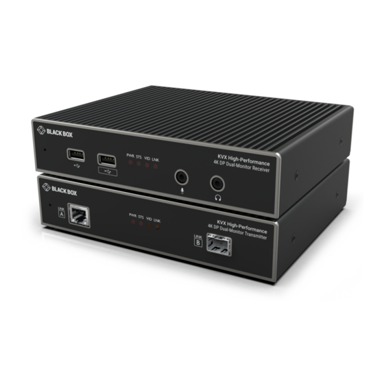
NEED HELP? LEAVE THE TECH TO US LIVE 24/7 TECHNICAL SUPPORT 1.877.877.2269 KVX-HP 100-SERIES FEATURES The transmitter and receiver modules are contained within slimline metal casings that measure just 186 x 152 x 40mm. KVX-HP 100-SERIES TRANSMITTER MODULE Recessed CATx port Status indicators SFP slot Provides an... - Page 9 NEED HELP? LEAVE THE TECH TO US LIVE 24/7 TECHNICAL SUPPORT 1.877.877.2269 KVX-HP 100-SERIES RECEIVER MODULE PWR STS VID LNK Recessed Audio ports USB ports Status indicators Connect your These provide Connect your micro- reset but- USB keyboard, visual confirma- phone and head- phones.
-
Page 10: Kvx-Hp 200-Series Features
NEED HELP? LEAVE THE TECH TO US LIVE 24/7 TECHNICAL SUPPORT 1.877.877.2269 KVX-HP 200-SERIES FEATURES The transmitter and receiver modules are contained within slimline metal casings that measure just 186 x 152 x 40mm. KVX-HP 200-SERIES TRANSMITTER MODULE Recessed CATx port Status indicators SFP slot Provides an... - Page 11 NEED HELP? LEAVE THE TECH TO US LIVE 24/7 TECHNICAL SUPPORT 1.877.877.2269 KVX-HP 200-SERIES RECEIVER MODULE Recessed USB ports Status indicators Audio ports Connect your The left port supports These provide reset but- microphone and keyboard, mouse visual confirma- and other USB HID tion of various headphones.
-
Page 12: Chapter 3: Installation
NEED HELP? LEAVE THE TECH TO US LIVE 24/7 CHAPTER 3: INSTALLATION TECHNICAL SUPPORT 1.877.877.2269 LOCATIONS Please consider the following important points when planning the position of the modules: • Situate the transmitter module close to the system to which it will be connected and near to a source of mains power. Place the receiver module in similar close proximity to the peripherals that it will connect with, plus a source of mains power. -
Page 13: Transmitter Usb Links
NEED HELP? LEAVE THE TECH TO US LIVE 24/7 TECHNICAL SUPPORT 1.877.877.2269 TRANSMITTER USB LINKS The transmitter module has two USB input ports on its rear panel: REMOTE The ports have different functions depending on the model of extender that you are using: USB HID (Human Interface Device) USB audio feed to/from the analog audio ports 100-series... -
Page 14: Transmitter Audio Links
NEED HELP? LEAVE THE TECH TO US LIVE 24/7 TECHNICAL SUPPORT 1.877.877.2269 TRANSMITTER AUDIO LINKS The modules support analog stereo audio in and out connections. Where necessary, make connections between the audio input and/or output ports of the host computer and the transmitter module. Note: Digital audio is also supported separately via the DisplayPort connectors as a transparent link- through. -
Page 15: Transmitter Power Connection
NEED HELP? LEAVE THE TECH TO US LIVE 24/7 TECHNICAL SUPPORT 1.877.877.2269 TRANSMITTER POWER CONNECTION There is no on/off switch on either of the modules, so operation begins as soon as power is applied. The power adapters supplied with the modules use locking-type plugs to help prevent accidental disconnections;... -
Page 16: Linking
NEED HELP? LEAVE THE TECH TO US LIVE 24/7 TECHNICAL SUPPORT 1.877.877.2269 LINKING The extender modules can be linked using either: • CATx (see below), or • Fiber (see next page) When fiber is used there are no limits to the resolutions that can be transferred, up to the maximum 4K (4096 x 2160); when a CATx link is used, the maximum resolution for dual head installations on 200-series models will be WQXGA (2560 x 1600). -
Page 17: Fiber Optic Link
Note: In order to maintain a high level of confidence in the fiber optic link, it is recommended that Black Box supplied SFPs are used. If alternative 10G SFP+ parts are used with LC connectors, the system will detect this and will flash the front panel LNK indicator. - Page 18 NEED HELP? LEAVE THE TECH TO US LIVE 24/7 TECHNICAL SUPPORT 1.877.877.2269 TO REMOVE AN SFP MODULE 1 If fitted, remove the dual fiber optic connectors from the SFP module (press in the release tab of the fiber optic connectors to disengage them).
-
Page 19: Receiver Video Display(S)
NEED HELP? LEAVE THE TECH TO US LIVE 24/7 TECHNICAL SUPPORT 1.877.877.2269 RECEIVER VIDEO DISPLAY(S) Two DisplayPort sockets are provided on the rear panel of each receiver module. On 100-series models, the signal from port 1 is duplicated on port 2. On 200-series models, ports 1 and 2 operate independently to supply the signals introduced to video ports 1 and 2 on the transmitter. -
Page 20: Receiver Audio Devices
NEED HELP? LEAVE THE TECH TO US LIVE 24/7 TECHNICAL SUPPORT 1.877.877.2269 RECEIVER AUDIO DEVICES The receiver module can support multiple analog audio devices, such as stereo headphones, a mono microphone or line-level in/ out connections. USB audio is also supported when the left hand USB socket on the receiver rear panel is connected to the computer. The audio signals received from the computer will be transferred to the analog audio sockets on the receiver. -
Page 21: Receiver Usb Devices
NEED HELP? LEAVE THE TECH TO US LIVE 24/7 TECHNICAL SUPPORT 1.877.877.2269 RECEIVER USB DEVICES Each receiver module contains a USB hub that can support multiple v2.0 or v1.1 USB HID (Human Interface Device) peripherals. On 100-series models, all four USB sockets are identical in operation. However, on 200-series models, three of the USB sockets are used for HID peripherals while the fourth, labeled (on the front panel) is a fully transparent USB port capable of supporting a wider range of devices. -
Page 22: Receiver Remote Port
NEED HELP? LEAVE THE TECH TO US LIVE 24/7 TECHNICAL SUPPORT 1.877.877.2269 RECEIVER REMOTE PORT The Remote port has a dual role, it can either: • Allow an optional remote control to be connected to the module, or • Create an RS232 serial connection with the receiver module. When serial devices are attached to the Remote ports on the transmitter and receiver modules, the units transparently convey the signals between them at rates up to 115200 baud - no serial configuration is required. -
Page 23: Receiver Power Connection
NEED HELP? LEAVE THE TECH TO US LIVE 24/7 TECHNICAL SUPPORT 1.877.877.2269 RECEIVER POWER CONNECTION There is no on/off switch on either of the modules, so operation begins as soon as power is applied. The power adapters supplied with the modules use locking-type plugs to help prevent accidental disconnections;... -
Page 24: Chapter 4: Configuration
NEED HELP? LEAVE THE TECH TO US LIVE 24/7 TECHNICAL CHAPTER 4: CONFIGURATION SUPPORT 1.877.877.2269 ACCESSING THE DASHBOARD The modules generally configure themselves automatically, collecting EDID information from the attached monitor(s) and passing the details to the host computer. Unless an issue is encountered, the modules will begin working together correctly as soon as they are connected. -
Page 25: Choosing The Dual Head Mode (200-Series Models Only)
NEED HELP? LEAVE THE TECH TO US LIVE 24/7 TECHNICAL SUPPORT 1.877.877.2269 CHOOSING THE DUAL HEAD MODE (200-series models only) When the CATx link is used to connect the transmitter and receiver modules, the available bandwidth is reduced. On 200-series models, if dual high resolution video displays are used, you can determine how the available bandwidth is shared between them. -
Page 26: Upgrading Firmware
SUPPORT 1.877.877.2269 UPGRADING FIRMWARE Firmware upgrades are periodically made available for products via the Black Box support department. Use this procedure to upgrade the firmware in both extenders. TO UPGRADE THE FIRMWARE 1 Download the firmware from the blackbox.com website or contact Tech Support to access the file. -
Page 27: Chapter 5: Operation
NEED HELP? LEAVE THE TECH TO US LIVE 24/7 CHAPTER 5: OPERATION TECHNICAL SUPPORT 1.877.877.2269 The modules are designed to be transparent in operation; all peripherals should respond exactly as they would when situated next to your host computer. INDICATORS The transmitter and receiver modules contain various indicators to provide you with status information. -
Page 28: Chapter 6: Further Information
NEED HELP? LEAVE THE TECH TO US LIVE 24/7 CHAPTER 6: FURTHER INFORMATION TECHNICAL SUPPORT 1.877.877.2269 APPENDIX 1 - REMOTE PORT PIN-OUT port uses a 6p6c socket. The pin-out is listed below. REMOTE Note: Although the pins labeled ‘Not used’ is inactive, it is still connected internally and so no links should be made at all to this pin. -
Page 29: Safety Information
NEED HELP? LEAVE THE TECH TO US LIVE 24/7 SAFETY INFORMATION TECHNICAL SUPPORT 1.877.877.2269 • For use in dry, oil free indoor environments only. • Do not use to link between buildings. • Ensure that the twisted pair interconnect cable is installed in compliance with all applicable wiring regulations. •... - Page 30 NEED HELP? LEAVE THE TECH TO US LIVE 24/7 TECHNICAL SUPPORT 1.877.877.2269 KVX-HP-100/200, rev. 1.6 © COPYRIGHT 2021 BLACK BOX CORPORATION. ALL RIGHTS RESERVED. 877-877-2269 | blackbox.com...
Need help?
Do you have a question about the KVXHP-100 and is the answer not in the manual?
Questions and answers