
Related Manuals for Xantrex RC7 - REV 1


Summary of Contents for Xantrex RC7 - REV 1
-
Page 1: Remote Controls
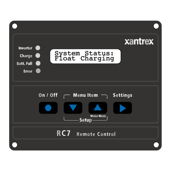
System Status: Float Charging RC7GS Installation and Operator’s Manual Xantrex RV Series Remote Controls... -
Page 2: Contact Information
RC7 & RC7GS Remote Controls Notice of Copyright Xantrex RC7 and RC7GS Remote Controls Installation and Operator’s Manual © October 2002 Xantrex International. All rights reserved. Xantrex is a registered trademark of Xantrex International. Disclaimer UNLESS SPECIFICALLY AGREED TO IN WRITING, XANTREX TECHNOLOGY INC. -
Page 3: Table Of Contents
RC7 & RC7GS Remote Controls RC7 & RC7GS Remote Controls Table of Contents Section Description Page Introduction ............... 1 Features ............. 1 ON/OFF Control Meters Controls Status Monitoring Installation ..............3 Operation ..............5 Front Panel ............. 5 Indicators and Controls Status LEDs Inverter LED Charge LED... - Page 4 RC7 & RC7GS Remote Controls Operation (continued) RC7GS Setup Menu ..........14 Set Clock (RC7GS Only) Select Genset Generator Start Generator Stop Begin Gen Quiet and End Gen Quiet Saving your Setup Choices ......... 18 RC7 and RC7GS System Status Displays ..19 AC Source Messages ........
- Page 5 RC7 & RC7GS Remote Controls Operation (continued) System Status Messages ........31 Battery State of Charge Time Left to Run Time Left to Charge Set Shore Power Generator Start/Stop Generator Connection .......... 33 Onan Quiet Diesel Power Tech Wiring Diagrams (2 and 3-wire) Power Tech 2-wire Power Tech 3-wire RC7 and RC7GS Setup Menu ......
-
Page 6: Important Safety Instructions
RC7 & RC7GS Remote Controls IMPORTANT SAFETY INSTRUCTIONS This manual contains important safety instructions that should be followed during the installation and maintenance of this product. To reduce the risk of electrical shock, and to ensure the safe installation and operation of this product, the following safety symbols have been placed throughout this manual to indicate dangerous conditions and important safety instructions. -
Page 7: 1.0 Introduction
RC7 & RC7GS Remote Controls 1.0 INTRODUCTION Features The RC7 and RC7GS (Generator Start) are control units that allow remote operation of any RV Series Inverter/Chargers rated from 2000 to 3000 watts. NOTE: The inverter and remote control must have software version 1.3x. The RC7 and RC7GS feature: •... -
Page 8: On/Off Control
RC7 & RC7GS Remote Controls 1.0 INTRODUCTION All operating controls and indicators for the RC7 and RC7GS are located on the front panel of the remote control. The inverter, software Rev. 1.3x must be installed in both the inverter and remote. Refer to the instructions in the RVU-2 Software Upgrade Kit manual if an upgrade is required. -
Page 9: 2.0 Installation
RC7 & RC7GS Remote Controls 2.0 INSTALLATION Installation Procedure: Select an appropriate location to install the remote control. Refer to the drawing (Figure 2) for hole and cutout dimensions or install the remote in a standard double-gang outlet box. Run the cable between the RC7 remote and the inverter/charger. Do NOT use standard telephone cable. - Page 10 RC7 & RC7GS Remote Controls 2.0 INSTALLATION “REMOTE CONTROL” RJ11 Connector RJ11 Connector ON/OFF Switch Inverter/Charger RC7 RC7GS Remote Control (back view) Figure 3 Remote Control Connectors Connect the communications cable into the RJ11 port on the inverter/ charger marked “REMOTE CONTROL.” Connect the other end of the cable into the jack on the remote (Figure 3).
-
Page 11: 3.0 Operation
RC7 & RC7GS Remote Controls 3.0 OPERATION Front Panel Indicators and Controls The RC7 and RC7GS front panels contain LEDs, LCD display and push- buttons for viewing status and system setup. All operating power for the remote control is provided by the inverter/charger via the supplied cable. Alphanumeric LCD Display Panel Status LEDs Inverter (green) -
Page 12: Inverter Led
RC7 & RC7GS Remote Controls 3.0 OPERATION Inverter LED The green Inverter LED indicates the inverter is switched ON and ready to provide backup power. If there is no AC power, the inverter LED will be ON solid, indicating that the inverter/charger is in the inverter (ON) mode. Inverter LED Other LEDs or Devices Meaning... -
Page 13: Lcd Display
RC7 & RC7GS Remote Controls 3.0 OPERATION LCD Display The LCD display is a 16 x 2 lines (32 characters total) back lit, alphanu- meric display, used for setting up the system operation as well as viewing current status or error messages. You can scroll through the display items by using the push-buttons below the display. -
Page 14: Setup/Menu Item Push-Button
RC7 & RC7GS Remote Controls 3.0 OPERATION Setup/Menu Item Push-button The Setup/Menu Item push-buttons accesses the system setup menus. Press and hold both push-buttons for approximately 5 seconds or until the display clears, then release the buttons. Press the UP or DOWN arrow buttons to scroll through the menu items. -
Page 15: Rc7 And Rc7Gs Setup Menu
RC7 & RC7GS Remote Controls 3.0 OPERATION RC7 and RC7GS Setup Menu The Setup menu configures the RC7 and RC7GS to specific operating system parameters. To access the Setup menu press and hold the UP and DOWN arrows push-buttons for approximately 5 seconds until the LCD display clears. - Page 16 RC7 & RC7GS Remote Controls 3.0 OPERATION Auto LBCO Automatic Low Battery Cut Out (Auto LBCO) prevents the inverter from draining the batteries below 10.9 V DC (with no load on the output). When this mode is enabled (ON), the inverter shuts OFF when the batteries reach 10.9 V DC.
- Page 17 RC7 & RC7GS Remote Controls 3.0 OPERATION Battery Type To ensure the batteries are receiving the proper charge voltage, the Battery Type must be selected for the type of batteries used in the system: GEL Cell, Liquid Lead Acid and AGM. The default setting is GEL Cell. This voltage varies depending on the batteries used, as specified below.
- Page 18 RC7 & RC7GS Remote Controls 3.0 OPERATION Set Shore Power The inverter monitors the AC power being drawn by both the battery charger and the AC loads connected to the inverter. If the current draw ap- proaches the shorepower circuit breaker rating, the battery charger reduces the amount of current supplied to the batteries to provide the maximum current to the AC loads.
- Page 19 RC7 & RC7GS Remote Controls 3.0 OPERATION LCD Contrast The LCD Contrast menu adjusts the contrast to accommodate changing lighting conditions and viewing angle. The default setting is Max. Contrast. LCD Contrast: LCD Contrast: LCD Contrast: LCD Contrast: • • • • •...
-
Page 20: Rc7Gs Setup Menu
RC7 & RC7GS Remote Controls 3.0 OPERATION RC7GS Setup Menu The RC7GS (Generator Start) features several additional setup menu selections related to automatic generator starting, stopping and generator quiet time. Figure 23 RC7GS Front Panel Set Clock (RC7GS only) Some generator functions are based on the time of day. The clock must be properly set to ensure the programmed function will perform at the correct time. -
Page 21: Select Genset
RC7 & RC7GS Remote Controls 3.0 OPERATION Select Genset After setting the clock, press the UP arrow once to access the Select Genset menu. Select the type and model of the generator by pressing the Settings push-button (RIGHT arrow) until the genset’s name and model is displayed in the LCD readout. -
Page 22: Generator Stop
RC7 & RC7GS Remote Controls 3.0 OPERATION The generator can be started or stopped at any time by pressing the DOWN arrow push-button (User Menu) until the Gen Start/Stop menu is displayed. Press and hold the On/Off push-button on the RC7GS front panel until the generator starts or stops. -
Page 23: Begin Gen Quiet And End Gen Quiet
RC7 & RC7GS Remote Controls 3.0 OPERATION Begin Gen Quiet and End Gen Quiet The period of time during which the generator is prevented from starting automatically can be defined using the RC7GS. To specify the begin quiet time, scroll to the Begin Gen Quiet: 00:00 by using the UP and DOWN arrow push-buttons. -
Page 24: Saving Your Setup Choices
RC7 & RC7GS Remote Controls 3.0 OPERATION Saving Setup Choices Once the setup options are complete, press and hold both the UP and DOWN arrow push-buttons until the display clears (approximately 5 seconds). The setup choices will be saved in nonvolatile memory 20 seconds after exiting the Setup menu if no other actions are taken. -
Page 25: Rc7 And Rc7Gs System Status Displays
RC7 & RC7GS Remote Controls 3.0 OPERATION RC7 and RC7GS System Status Displays The RC7 and RC7GS remote controls display the operating mode and system status by lighting one or more LEDs located on the front panel and/or by displaying a message on the LCD display. The four LEDs reflect the same information as the single tricolored LED on the inverter/charger. -
Page 26: Starter Cooldown And Gen Start
RC7 & RC7GS Remote Controls 3.0 OPERATION Once the generator starts, there is a brief delay to allow the genset to reach operating speed and for the inverter/charger to synchronize to the generator, at which point the LCD display shows that AC is again available. Genset Status: AC Available Figure 35... -
Page 27: Low Ac Input
RC7 & RC7GS Remote Controls 3.0 OPERATION Inverter Buzzer Sounds Genset Status: Charge Gen Quiet Fault Batt. Full Red Error LED Lights and Error Message Appears in the LCD Error Display and buzzer sounds. 822-4A-001 Figure 38 Gen Quiet Fault Error Message NOTE: Press any arrow push-button to cancel the buzzer. - Page 28 RC7 & RC7GS Remote Controls 3.0 OPERATION Inverter Mode Messages When the inverter is ON (no AC present), it is either inverting or measuring the AC output circuits for a load meeting the specifications set up in the Search Sense menu selection (Figure 12 and 13), (if the Search Mode is selected). When the inverter is in the Search mode, “Searching”...
-
Page 29: Charger Mode Messages
RC7 & RC7GS Remote Controls 3.0 OPERATION Charger Mode Messages When AC (shorepower) is available, the inverter/charger automatically switches to the charger mode. There are four separate charger modes: Bulk, Absorption, Float and Equalization. Refer to the inverter/charger operator’s manual for details on charger modes. Bulk Charging When the charger is charging in the Bulk mode, the LCD will display “Bulk Charging”... -
Page 30: Equalizing Charging
RC7 & RC7GS Remote Controls 3.0 OPERATION Equalizing Charging (Liquid Lead Acid and AGM Batteries ONLY) To activate the Equalize mode, press and hold the Settings push-button (RIGHT arrow) until the LCD display clears and “Equalizing” appears (approximately 6 seconds). The Charge LED will increase its flashing rate to approximately 8 flashes per second (flickering). -
Page 31: Inverter/Charger Error Messages
RC7 & RC7GS Remote Controls 3.0 OPERATION Inverter/Charger Error Messages Error messages display when a fault is detected with either the inverter or charger. The red Error LED lights, and the buzzer sounds. Error messages for the inverter/charger display the error condition as well as a suggested remedy. Over Temperature The “Otemp / Less Load”... -
Page 32: High Battery Voltage
RC7 & RC7GS Remote Controls 3.0 OPERATION High Battery Voltage The “Hibat/Stop Chrg” System Status message is displayed when the battery voltage is too high. Switch off any other charging sources to allow the voltage level to drop. The inverter automatically resets and resumes operation when the battery reaches a safe voltage level. -
Page 33: Dcld Lockout Error
RC7 & RC7GS Remote Controls 3.0 OPERATION DCLD Lockout Error The “DCLD Lockout Err” System Status message is displayed when the +12 V DC supplied to the “DCLD” input wire of the inverter/charger is lost and the DCLD feature is activated. In addition, the red Error LED will light and the buzzer will sound for approximately four minutes. -
Page 34: Meters Display
RC7 & RC7GS Remote Controls 3.0 OPERATION Meters Display The RC7 and RC7GS have built-in meters that monitor inverter/charger activities. To view these meters, press and hold the Meter Mode push-button (UP arrow) for five seconds until the display clears. Use the DOWN arrow push- button to scroll through the meter displays. - Page 35 RC7 & RC7GS Remote Controls 3.0 OPERATION AC Output Voltage This meter displays the actual inverter AC output voltage measured at the AC output. When in the charger mode, the meter will read “0 VAC.” Search mode is indicated by “< 40 VAC” appearing in the display. Inverter Output: 0 VAC Figure 56...
- Page 36 RC7 & RC7GS Remote Controls 3.0 OPERATION Transformer Temperature This meter displays the internal temperature of the inverter/charger’s transformer. The scale is divided into counts, which do not directly correspond to the Fahrenheit or Celsius temperature scale. A higher reading indicates a lower temperature.
-
Page 37: System Status Messages
RC7 & RC7GS Remote Controls 3.0 OPERATION System Status Messages After installing the RC7/RC7GS, the LCD screen displays operating system status messages which is the default screen after exiting all other setting or meter functions. Operating parameters include; Battery State-of-charge (SOC), Time Remaining to Run, Time Left to Charge and Set Shorepower. -
Page 38: Time Left To Charge
RC7 & RC7GS Remote Controls 3.0 OPERATION Time Left to Charge This meter displays the estimated hours required to charge the batteries to full capacity. The meter is accurate to 1/10 of an hour (6 minutes). Time Left to Charge: x.x Hours Figure 64 Time Left to Charge Display... -
Page 39: Generator Connection
RC7 & RC7GS Remote Controls 3.0 OPERATION Generator Connection (RV Series only) Proper installation and setup of the AC generator is essential for the correct operation of the inverter/charger. The RC7GS contains the proper software code to work with various generators listed in the LCD display. NOTE: The RV Series Inverter/Charger must be at Software Rev. -
Page 40: Power Tech Wiring Diagrams (2 And 3-Wire)
RC7 & RC7GS Remote Controls 3.0 OPERATION Power Tech Wiring Diagrams (2 and 3-wire) Before wiring for the Power Tech option, read all instructions and cautionary markings located in the RV Series Inverter/Charger Operator’s manual. NOTE: Rev. 1.3x must be installed in both the inverter and RC7GS remote. Both 2-wire and 3-wire Power Tech Generators require a B+ (Battery Positive) wire from the generator to the inverter to indicate the generator is running. -
Page 41: Power Tech 2-Wire
RC7 & RC7GS Remote Controls 3.0 OPERATION Power Tech 2-wire Connect the generator as shown below. COM. GEN START 1 RED (from start/stop switch) N.O. GEN START 2 WHITE/RED (from start/stop switch) N.C. GEN RUN 3 COM. GENRUN 1 N.O. GEN RUN 2 2-WIRE CONFIGURATION INVERTER/CHARGER 822-4A-009... -
Page 42: Rc7 And Rc7Gs Setup Menu
RC7 & RC7GS Remote Controls 3.0 OPERATION RC7 and RC7GS Setup Menu Press and hold both menu item keys for 5 seconds Search Sense: Search Sense: Search Sense: Search Sense: Search Sense: Defeat ...40 W load About 5W load ...10 W load >... -
Page 43: Rc7 And Rc7Gs User Menu
RC7 & RC7GS Remote Controls 3.0 OPERATION RC7 and RC7GS Users Menu System Status Messages AC Source Inverter Mode Charger Mode Error Mode System Status: System Status: System Status: System Status: Waiting for AC Searching Bulk Charging Otemp / Less Load System Status: System Status: System Status:... -
Page 44: Storage Checklist
RC7 & RC7GS Remote Controls 3.0 OPERATION Storage Checklist NOTE: This applies only to the RV Series Inverter/Charger with RC7GS Remote. Proper storage procedures extend the life of the batteries and ensure that the coach is ready for operation when needed. The following checklist is for battery-related storage activities. -
Page 45: 4.0 Limited Warranty
RC7 & RC7GS Remote Controls 4.0 LIMITED WARRANTY What does this warranty cover? This Limited Warranty is provided by Xantrex Technology, Inc. (“Xantrex”) and covers defects in workmanship and materials in your Xantrex RC7 and RC7GS Remote Controls. This warranty lasts for a Warranty Period of 12 months from the date of purchase at point of sale to you, the original end user customer. - Page 46 RC7 & RC7GS Remote Controls IN NO EVENT WILL XANTREX BE LIABLE FOR ANY SPECIAL, DIRECT, INDIRECT, INCIDENTAL OR CONSEQUENTIAL DAMAGES, LOSSES, COSTS OR EXPENSES HOWEVER ARISING WHETHER IN CONTRACT OR TORT INCLUDING WITHOUT RESTRICTION ANY ECONOMIC LOSSES OF ANY KIND, ANY LOSS OR DAMAGE TO PROPERTY, ANY PERSONAL INJURY, ANY DAMAGE OR INJURY ARISING FROM OR AS A RESULT OF MISUSE OR ABUSE, OR THE INCORRECT INSTALLATION, INTEGRATION OR OPERATION OF THE PRODUCT.
- Page 47 RC7 & RC7GS Remote Controls...
- Page 48 Xantrex Technology Inc. Toll free 1 800 670 0707 Direct 1 604 422 2777 Fax 1 604 420 2145 CustomerService@xantrex.com www.xantrex.com 975-0050-01-01 Rev. 1 Printed in the U.S.A.
Need help?
Do you have a question about the RC7 - REV 1 and is the answer not in the manual?
Questions and answers