
Related Manuals for Taylor M9


Summarization of Contents
GENERAL INFORMATION
MANUFACTURERS DETAILS
Company name, address, and contact information for Taylor Studwelding Systems Ltd.
MANUAL PURPOSE AND CONTENT
Outlines the intended audience and scope of information covered in this operating guide.
INTRODUCTION TO STUD WELDING
CAPACITOR DISCHARGE PROCESS EXPLAINED
Details the fundamental principles and operational mechanics of Capacitor Discharge stud welding.
EQUIPMENT SPECIFICATIONS
AVAILABLE EQUIPMENT MODELS
Lists the CD stud welding equipment models and their corresponding part numbers.
ACCESSORIES INFORMATION
Refers users to the pistol's operating guide for available accessory options.
EXTERNAL UNIT FEATURES
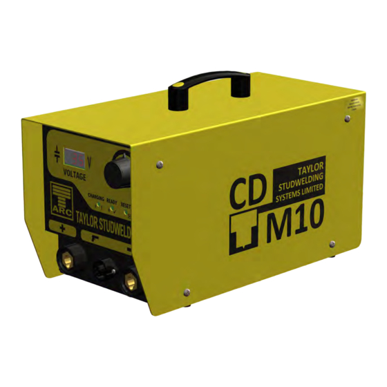
FRONT PANEL COMPONENTS OVERVIEW
Identifies and explains the controls, indicators, and displays on the front panel.
INDICATOR LED FUNCTIONS EXPLAINED
Describes the meaning and status indications of the READY, CHARGING, and RESET LEDs.
EXTERNAL UNIT FEATURES (continuation)
REAR PANEL COMPONENTS IDENTIFIED
Details the connectors, labels, and components located on the rear panel.
CRITICAL OPERATIONAL AND SAFETY NOTES
Essential instructions for safe and correct operation of the welding equipment.
SAFETY GUIDELINES AND PRECAUTIONS
ELECTRICAL HAZARDS AND PROTECTION
Covers electrical risks, capacitor energy storage, and safe cleaning practices.
FIRE AND EXPLOSION PREVENTION
Addresses fire risks from hot metal spatter and precautions with combustible materials.
OPERATIONAL ENVIRONMENT LIMITATIONS
Specifies conditions and environments where the equipment should not be operated.
SAFETY GUIDELINES AND PRECAUTIONS (continuation)
PERSONNEL HEALTH AND SAFETY
Protects operators from arc rays, fumes, noise, and magnetic fields.
EQUIPMENT MAINTENANCE SAFETY PROCEDURES
Guidelines for safely inspecting and maintaining cables and electrical connections.
AUTHORIZED PERSONNEL AND TRAINING REQUIREMENTS
Emphasizes the necessity of trained and authorized operators for equipment use.
SAFETY GUIDELINES AND PRECAUTIONS (continuation)
SAFE EQUIPMENT INSTALLATION PRACTICES
Covers safe site selection, installation, and cable routing procedures.
ELECTROMAGNETIC INTERFERENCE CONSIDERATIONS
Information regarding electromagnetic emissions and compliance with relevant standards.
EQUIPMENT DISPOSAL AND ENVIRONMENTAL IMPACT
Provides guidance on the proper disposal of the equipment and its components.
SETTING UP AND OPERATING THE WELDER
INITIAL CONTROL UNIT SETUP AND CONNECTION
Steps for positioning the control unit and connecting mains power and earth cables.
CORRECT EARTH CLAMP ATTACHMENT
Proper technique for attaching earth clamps to the workpiece for optimal conductivity.
SETTING UP AND OPERATING THE WELDER (continuation)
SELECTING AND CONNECTING THE WELDING PISTOL
Guidance on choosing the correct welding pistol and connecting its cables securely.
PISTOL SETUP AND SECURING MECHANISM
Instructions for correctly positioning the pistol and locking its connectors.
SETTING UP AND OPERATING THE WELDER (continuation)
UNIT POWER-ON AND VOLTAGE SETTING
Procedure for switching on the unit and adjusting the welding voltage via the selector knob.
WELDING POSITIONING AND TRIGGER ACTIVATION
How to position the stud and workpiece, then press the trigger to perform a weld.
POST-WELD PISTOL LIFTING TECHNIQUE
Correct method for lifting the pistol vertically after welding to prevent damage to the chuck.
SETTING UP AND OPERATING THE WELDER (continuation)
VISUAL INSPECTION OF WELD QUALITY
How to visually assess weld quality, identifying good welds and spatter.
IDENTIFYING COMMON WELD DEFECTS
Explains characteristics and causes of cold, hot, and arc blow weld defects.
PERFORMING WELD STRENGTH BENDING TESTS
Describes bending test procedures to verify the strength and integrity of the weld.
WELD SETTING RECOMMENDATIONS
OVERVIEW OF SETTING CHARTS
Introduces the suggested welding settings for CD-M models, materials, and stud types.
MATERIAL AND THICKNESS GUIDELINES
Lists the materials and sheet thicknesses for which setting charts are provided.
IMPORTANCE OF SAMPLE WELDS
Advises users that settings are a guide and sample welds on actual material are recommended.
WELD SETTINGS FOR CD-M8
CD-M8 CONTACT WELDING SETTINGS
Table of recommended voltage and spring settings for CD-M8 contact welding applications.
CD-M8 LIFT GAP WELDING SETTINGS
Table of recommended voltage and lift settings for CD-M8 lift gap welding applications.
WELD SETTINGS FOR CD-M8 (continuation)
CD-M8 CONTACT SETTINGS (M6-M10)
Extended contact settings for CD-M8, covering larger stud sizes and accessory brackets.
CD-M8 LIFT GAP SETTINGS (M6-M10)
Extended lift gap settings for CD-M8, covering larger stud sizes and accessory brackets.
WELD SETTINGS FOR CD-M9
CD-M9 CONTACT WELDING SETTINGS
Table of recommended voltage and spring settings for CD-M9 contact welding applications.
CD-M9 LIFT GAP WELDING SETTINGS
Table of recommended voltage and lift settings for CD-M9 lift gap welding applications.
WELD SETTINGS FOR CD-M9 (continuation)
CD-M9 CONTACT SETTINGS (M6-M10)
Extended contact settings for CD-M9, covering larger stud sizes and accessory brackets.
CD-M9 LIFT GAP SETTINGS (M6-M10)
Extended lift gap settings for CD-M9, covering larger stud sizes and accessory brackets.
WELD SETTINGS FOR CD-M10
CD-M10 CONTACT WELDING SETTINGS
Table of recommended voltage and spring settings for CD-M10 contact welding applications.
CD-M10 LIFT GAP WELDING SETTINGS
Table of recommended voltage and lift settings for CD-M10 lift gap welding applications.
WELD SETTINGS FOR CD-M10 (continuation)
CD-M10 CONTACT SETTINGS (M6-M10)
Extended contact settings for CD-M10, covering larger stud sizes and accessory brackets.
CD-M10 LIFT GAP SETTINGS (M6-M10)
Extended lift gap settings for CD-M10, covering larger stud sizes and accessory brackets.
METHODS FOR STUD LOCATION
TYPES OF STUD LOCATION ASSEMBLIES
Describes tripod leg, nose cone, and extended leg assemblies for stud placement.
WARNING: AVOID MANUAL CENTRE PUNCHES
Critical warning against using manual centre punch indentations for stud location.
WELD QUALITY ASSESSMENT AND TESTING
VISUAL WELD INSPECTION CRITERIA
Guidance on visually assessing weld quality based on material witness and appearance.
MECHANICAL TESTING PROCEDURES
Explains bending and torsion tests for verifying weld strength and integrity.
COMPONENT BREAKDOWN CD-M CONTROLLER
EXTERNAL CASING AND IDENTIFICATION PARTS
Exploded view and parts list for the controller's outer casing, handle, and identification stickers.
COMPONENT BREAKDOWN INTERNAL STRUCTURE
MAIN CHASSIS AND ASSOCIATED HARDWARE
Exploded view of the main chassis and associated hardware such as washers and screws.
COMPONENT BREAKDOWN FRONT PANEL ELECTRONICS
KNOBS, OVERLAYS, AND PRINTED CIRCUIT BOARDS
Exploded view and parts list for front panel electronics like knobs, overlays, and PCBs.
COMPONENT BREAKDOWN CAPACITOR BANK (PART 1)
INITIAL CAPACITOR BANK ASSEMBLY COMPONENTS
Exploded view of the initial parts and hardware for the capacitor bank assembly.
COMPONENT BREAKDOWN CAPACITOR BANK (PART 2)
CAPACITOR BANK BUSBARS AND WIRING HARDWARE
Detailed parts list for capacitor bank components including busbars, screws, and nuts.
COMPONENT BREAKDOWN CAPACITOR BANK (PART 3)
CAPACITOR BANK TRANSFORMER AND RELAY COMPONENTS
Exploded view of capacitor bank components such as the transformer, relays, and mounts.
COMPONENT BREAKDOWN CAPACITOR BANK (PART 4)
CAPACITOR BANK RECTIFIER AND TERMINAL COMPONENTS
Parts list for capacitor bank components including the rectifier, terminal blocks, and capacitors.
COMPONENT BREAKDOWN BASEPLATE ASSEMBLY
BASEPLATE AND MOUNTED COMPONENTS
Exploded view and parts list for the baseplate and its fitted components like sockets and feet.
COMPONENT BREAKDOWN REAR CASING AND FAN
REAR CASING, FAN, AND GUARD COMPONENTS
Exploded view and parts list for the rear casing, cooling fan, and protective guards.
COMPONENT BREAKDOWN REAR PANEL CONTROLS
SWITCHES, FUSE HOLDER, AND CABLE GLAND
Exploded view and parts list for rear panel controls like switches, fuse holder, and cable gland.
MAINS CORDSET SELECTION GUIDANCE
Information on selecting appropriate mains cordsets based on voltage and destination.
WIRING SCHEMATIC DIAGRAMS
STANDARD CONTACT CONTROLLER WIRING
Detailed wiring diagram for the standard contact controller models M8, M9, and M10.
WIRING SCHEMATIC DIAGRAMS (continuation)
LIFT GAP CONTROLLER WIRING DIAGRAM
Detailed wiring diagram for the lift gap controller models M8, M9, and M10.
WIRING SCHEMATIC DIAGRAMS (continuation)
CNC CONTACT CONTROLLER WIRING DIAGRAM
Detailed wiring diagram for the CNC contact controller models M8, M9, and M10.
WIRING SCHEMATIC DIAGRAMS (continuation)
CNC GAP CONTROLLER WIRING DIAGRAM
Detailed wiring diagram for the CNC gap controller models M8, M9, and M10.
EU DECLARATION OF CONFORMITY
PRODUCT CONFORMITY AND DIRECTIVE COMPLIANCE
Declaration of equipment compliance with EU directives and relevant European standards.
AUTHORIZED EUROPEAN REPRESENTATIVE DETAILS
Contact information for the authorized European representative as per the declaration.
Need help?
Do you have a question about the M9 and is the answer not in the manual?
Questions and answers