Sign In
Upload
Download
Table of Contents
Contents
Add to my manuals
Delete from my manuals
Share
URL of this page:
HTML Link:
Bookmark this page
Add
Manual will be automatically added to "My Manuals"
Print this page
×
Bookmark added
×
Added to my manuals
Manuals
Brands
Taylor Manuals
Battery Charger
M8
Operating manual
Taylor M8 Operating Manual
Compact capacitor discharge studwelding equipment
Hide thumbs
1
Table Of Contents
2
3
4
5
6
7
8
9
10
11
12
13
14
15
16
17
18
19
20
21
22
23
24
25
26
27
28
29
30
31
32
33
34
35
36
37
38
39
page
of
39
Go
/
39
Contents
Table of Contents
Bookmarks
Table of Contents
Table of Contents
General Information
Introduction
External Features
Setting up & Welding
Weld Settings
Methods of Stud Location
Weld Assessment/Testing
Front Panel
Baseplate
Declaration of Conformity
Advertisement
Quick Links
Download this manual
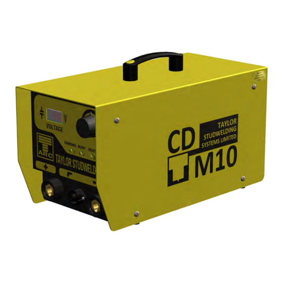
TAYLOR STUDWELDING
SYSTEMS LIMITED
OPERATING GUIDE
FOR
CD-M RANGE
OF
COMPACT CAPACITOR DISCHARGE
STUDWELDING EQUIPMENT
MODELS
M8, M9 & M10
VISIT OUR WEBSITE
V-21A
1
Table of
Contents
Previous
Page
Next
Page
1
2
3
4
5
Advertisement
Table of Contents
Need help?
Do you have a question about the M8 and is the answer not in the manual?
Ask a question
Questions and answers
Related Manuals for Taylor M8
Battery Charger Taylor M9 Operating Manual
Compact capacitor discharge studwelding equipment (39 pages)
Battery Charger Taylor M10 Operating Manual
Compact capacitor discharge studwelding equipment (39 pages)
Battery Charger Taylor CD-i Operating Manual
Capacitor discharge studwelding equipment (24 pages)
This manual is also suitable for:
M9
M10
Table of Contents
Print
Rename the bookmark
Delete bookmark?
Delete from my manuals?
Login
Sign In
OR
Sign in with Facebook
Sign in with Google
Upload manual
Upload from disk
Upload from URL


Need help?
Do you have a question about the M8 and is the answer not in the manual?
Questions and answers