
Related Manuals for EBARA E-drive 2200


Summarization of Contents
3. Technical Characteristics
3.1 Weight and dimensions
Details the weight and physical dimensions of the E-drive models.
4. Electric wiring
4.1 Protections
Protection needed before each E-drive, depending on installation and local norms.
4.2 Electromagnetic compliance
Measures for ensuring EMC compatibility of the system, including grounding and cable types.
4.3 Installation with long motor cables
Recommendations for installing with long motor cables, including switching frequency adjustment.
5. E-drive installation
Motor mounting kit
Details of the motor mounting kit for connecting the E-drive to the motor fan cover.
Wall mounting kit
Components of the kit for wall mounting the E-drive, including auxiliary fan.
5. E-drive for constant pressure control
5.1.1 Pressure tank
Guidelines for selecting the pressure tank volume and pre-charge pressure for system stability.
5.1.2 Pressure sensor
Requirements for the pressure sensor, including signal type and voltage.
6. E-drive Use and Programming
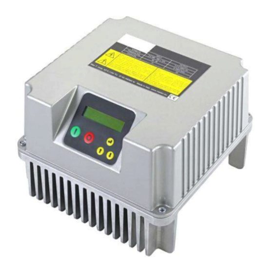
6.1 E-drive display
Description of the E-drive's LCD display, including status messages and indicators.
6.2 Initial configuration
Procedure for initial setup to configure pump and system parameters.
6.5 Installer parameters
Control mode
Defines the operating mode: constant value, fixed speed, or external speed control.
Unit
Specifies the unit of measurement for parameters, typically 'bar'.
6.6 Advanced parameters
Rated motor Volt.
Nominal motor voltage as per the motor nameplate.
Voltage boost
Relates to increasing voltage when starting the motor.
7. Protections and alarms
OVERCURRENT MOT.
Motor overload: motor input current exceeds nominal.
UNDER VOLTAGE
Too low voltage.
OVER VOLTAGE
Too high voltage.
OVER TEMP. INV.
Inverter too high temperature.
NO LOAD
No load, no motor operation.
NO WATER (DRY RUN COSPHI)
Engine's cos phi value is lower than the set dry run cos phi value.
SENSOR FAULT
Sensor error.
MAX. VALUE ALARM
Measured value reached the maximum allowed by the system.
MIN. VALUE ALARM
Measured value reached the minimum allowed by the system.
IGBT TRIP ALARM
Load current exceeds drive capacity.
NO COMMUNICATION
Lost communication between master and slave units.
ADDRESS ERROR
Same address as other E-drives in the group.
KEYBOARD FAULT
Keyboard button pressed for over 150 seconds.
ACTIVE DIG.IN.X
Digital input X open / closed.
ALARM SLAVE XX
Master unit detected an error in the slave unit.
8. Auxiliary pumps for constant pressure control
8.1 DOL pumps
Description of how DOL pumps are controlled via E-drive outputs.
8.2 COMBO Functionality
Master setup
Initial steps for setting up the E-drive system, including power and initial configuration.
9. Troubleshooting
LCD display not turning on after E-drive power-up
Troubleshooting steps for a blank or non-responsive E-drive LCD display.
E-drive power line interrupted by contactor differential protection
Troubleshooting steps for E-drive power interruption due to contactor differential protection.
When performing sensor check, 'SENSOR OFF' alarm occurs
Troubleshooting 'SENSOR OFF' alarm during sensor check procedure.
Frequency and pressure fluctuations in constant pressure control mode
Troubleshooting pressure and frequency fluctuations in constant pressure control.
Continuous stop/start of DOL pump
Troubleshooting continuous DOL pump cycling issues.
Measured pressure drops too much before E-Drive starts pump
Diagnosing and resolving issues where measured pressure drops significantly before pump starts.
Need help?
Do you have a question about the E-drive 2200 and is the answer not in the manual?
Questions and answers