Table of Contents
Advertisement
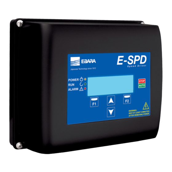
INVERTER FOR PUMPS
INVERTER FOR PUMPS
Instruction and maintenance manual.............................................................................................................
Instruction and maintenance manual.................................................................................................. 3
INVERTER PER ELETTROPOMPE
INVERTER PER ELETTROPOMPE
Manuale di istruzioni e manutenzione ..........................................................................................................
Manuale di istruzioni e manutenzione .............................................................................................. 31
VARIATEUR POUR POMPES ÉLECTRIQUES
VARIATEUR POUR POMPES ÉLECTRIQUES
Manuel d'instructions et de maintenance .....................................................................................................
INVERTER FÜR PUMPEN
INVERTER FÜR PUMPEN
Gebrauchs - und wartungsanleitung .............................................................................................................
Gebrauchs - und wartungsanleitung................................................................................................. 87
INVERSOR PARA BOMBAS ELÉCTRICAS
INVERSOR PARA BOMBAS ELÉCTRICAS
Manual de instrucciones y mantenimento ....................................................................................................
Manual de instrucciones y mantenimento .......................................................................................115
INVERTER VOOR ELEKTRISCHE POMPEN
Handleiding voor gebruik en onderhoud .......................................................................................................
Handleiding voor gebruik en onderhoud......................................................................................... 227
INVERSOR PARA BOMBAS ELÉTRICAS
Manual de instruções e manutenção ............................................................................................................
Manual de instruções e manutenção.............................................................................................. 255
FALOWNIK DO POMP
FALOWNIK DO POMP
Instrukcja Obsługi i Konserwacji ........................................................................................................
ИНВЕРТОР ДЛЯ ЭЛЕКТРИЧЕСКИХ НАСОСОВ
Инструкция по эксплуатации и обслуживанию .........................................................................................
INVERTOR PENTRU POMPE ELECTRICE
Manual de instrucțiuni și întreținere ..............................................................................................................
ELEKTRİK POMPALARI İÇİN İNVERTER
Kullanım ve bakım kılavuzu ..........................................................................................................................
............................................................................................................ 451
......................................................................................... 59
..................................................................................................... 367
................................................................................................ 423
25
47
69
91
113
135
157
.............................................. 395
179
201
223
EN
3
IT
FR
DE
ES
NL
PT
PL
RU
RO
TR
Advertisement
Table of Contents

Related Manuals for EBARA E-SPD Series


Summary of Contents for EBARA E-SPD Series
- Page 1 INVERTER FOR PUMPS INVERTER FOR PUMPS Instruction and maintenance manual......................Instruction and maintenance manual....................3 INVERTER PER ELETTROPOMPE INVERTER PER ELETTROPOMPE Manuale di istruzioni e manutenzione ......................Manuale di istruzioni e manutenzione ....................31 VARIATEUR POUR POMPES ÉLECTRIQUES VARIATEUR POUR POMPES ÉLECTRIQUES Manuel d’instructions et de maintenance .....................
- Page 3 INDEX 1. Presentation ..................................... 2. Safety rules ....................................... 3. Technical data ....................................4. Product identification ................................. 5. Size and weight ....................................6. Storage ........................................ 7. Installation and assembly ................................ 8. Electrical connections .................................. 9. Screen format ....................................10. Main screen ......................................
-
Page 4: Electrical Risk
1. PRESENTATION The following product is an electronic device for the control and protection of pump systems according to the fre- quency of the pump’s power supply. The inverter can be connected to any pump to manage its operation and main- tain a constant pressure. -
Page 5: Technical Data
- Although the pump is not operational (red POWER LED blinking), the electrical supply must still be cut off to the whole frequency converter for any maintenance work. If there are any anomalies in the installation, the frequency converter can be stopped manually using the button AUTO/STOP for this purpose. -
Page 6: Installation And Assembly
7. INSTALLATION AND ASSEMBLY Before installing the frequency inverter, carefully read the whole of this manual and consult the safety regulations in force in the country in which it will be used. The installation must be carried out by a qualified technician. a) Installation of the frequency converter: - It must be installed in a well ventilated area, protected from damp and direct exposure to the sun and rain. - Page 7 - The location of the pressure transducer must always be as close as possible to the pump unit, as close as possible to the membrane expander, and always after the general retention valve of the pump unit It is essential to install a general cut-off valve for the pump unit, after the physical location of the pressure transducer.
-
Page 8: Electrical Connections
8. ELECTRICAL CONNECTIONS 8. ELECTRICAL CONNECTIONS MT 2200 TT 4000 POWER SUPPLY POWER SUPPLY 230Vac 1~ 400Vac 3~ RELAY OUTPUT 2 RELAY OUTPUT 1 DIGITAL INPUT 2 DIGITAL INPUT 1 PRESSURE TRANSMITTER RS485 COMUNICATION FRONT PANEL MT 2200 MOTOR 230/400Vac TT 4000 MOTOR 230/400Vac E-SPD MT 2200... -
Page 9: Signal Connections
b) Signal connections Signal Description Outputs that act according to how the parameters 5.14 and 5.15 respectively have been programmed. Outputs relay 1 and 2 These outputs are potential free and have a maximum load of 5 amperes at 230 Vac. When wall-mounted, as there is no cooling from the motor’s own fan, the ventilation system of the wall mounting shall be used for this cooling. -
Page 10: Screen Format
9. SCREEN FORMAT Pump operation LED Frequency converter voltage LED Main display Manual stop button Alarm LED Left selection button Raise button Lower button Right selection button 10. MAIN SCREEN Current rotation frequency Instant consumption Nominal Consumption Stop frequency 4 8 . 9 ( 4 8 . -
Page 11: Operation Mode
11. OPERATION MODE The operation mode of the frequency converter will continuously seek to minimise the electricity demand, at the same time guaranteeing minimum wear to the pumps. a) Single pump unit: By the direct reading of the pressure transducer, the variable speed drive is responsible for managing the rotation speed of the electric motor of the pump, guaranteeing the mains pressure remains fixed and unaltered, regardless of the instantaneous demand for flow required. - Page 12 The system automatically indicates the number of frequency converters (x) that are connected to your network. It is an indicative parameter and cannot be modified. With F1 you can repeat the automatic search if the value shown “x” is different from the real value. If you perform various searches and the value still does not coincide, there is probably a connection error in the network of frequency converters.
- Page 13 In this point you must enter the nominal consumption of the motor, increasing or decrease the value using the arrow keys and validating with F2. NOTE: The nominal consumption is indicated on the specifications plate of the motor. You must choose the correct value, for example if you connect a frequency converter MT 2200 select the value 230 V and for TT 4000 400 V.
- Page 14 • Wait 10 seconds: It displays a ten-second countdown after which the next step to take will be indicated. This countdown will not start if the indicated pressure is above what we have set in the set pressure. If once the countdown starts the pressure increases too much, the counter will show the 10 seconds again until the pressure does not decrease.
-
Page 15: Setup Menu
13. SETUP MENU MENU 1. PARAMETERS 2. DISPLAY 3. LOG 4. MANUAL 5. ADVANCED PARAM. 6. FINE TUNING 2.01 MODULE 6.01 PROPORTIONAL 1.1 WORKING PRESSURE 5.01 LANGUAGE TEMPERATURE CONSTANT 1.2 MOTOR CURRENT 2.02 ANALOGUE SIGNAL 5.02 UNITS OF PRESSURE 6.02 INTEGRAL CONSTANT 5.03 MAXIMUM NUMBER OF 6.03 SWITCHING 1.3 ROTATION DIRECTION... - Page 16 1. PARAMETERS Programming Par. Description Units Notes Default Min. Max. WORKING PRESSURE Wizard Pressure you wish to maintain in the system. Current of the motor in amperes. Taking into account MOTOR CURRENT Wizard whether your motor is wired as three phase 230V or three phase 400V.
- Page 17 4. MANUAL The system is prepared to carry out speed and operation tests manually through this menu. When you access this menu, regardless of the status of the system, the unit from which you are accessing stops its functions and therefore stops the pump.
- Page 18 Programming Par. Description Units Notes Default Min. Max. MINIMUM WORKING Minimum frequency at which you allow the pump to 5.07 FREQUENCY work. MAXIMUM WORKING Maximum frequency at which you allow the pump 5.08 FREQUENCY to work. AUXILIARY OPERATING When the pump in operation reaches this frequency it 5.09 FREQUENCY sends a command to the auxiliary to start up.
- Page 19 Programación Par. Descripción Notas Defecto Min. Max. In this parameter you can choose not to have a schedule program (OFF) or the days of the week that you want this program to run. You can choose between M-Su whole weeks (M-Su), weekdays (M-F), weekends (Sa- 5.16 SCHEDULE PROGRAM 1 Su) or individual days.
- Page 20 6. FINE TUNING Programming Par. Description Units Notes Default Min. Max. 6.01 PROPORTIONAL CONSTANT 6.02 INTEGRAL CONSTANT 6.03 SWITCHING FREQUENCY 16.0 6.04 STOP SWITCHING RANGE 6.05 STOP SWITCHING SPEED If you change this parameter from “NO” to “YES” 6.09 ALARMS RESET you will reset the alarms log and the parameter automatically returns to “NO”.
- Page 21 WARNING REASON EXPLANATION / SOLUTION The start-up wizard is running. The LED will stop blinking once the initial configuration wizard has finished. The ALARM LED blinks. The pump is in a state of alarm Consult the section on Alarms in this (indicated on the display).
- Page 22 15. ALARMS MESSAGE REASONS SOLUTION(S) Check that the nominal consumption ALARM F01 data has been entered correctly. Indicates excessive consumption in the motor. OVERCURRENT Check that the pump rotates freely with no obstructions. Disconnect the motor from the frequency The motor is communicated or has converter and check that the message burnt out.
- Page 23 MESSAGE REASONS SOLUTION(S) Disconnect the motor from the frequency The motor is communicated or has converter and check that the message burnt out. disappears. If this is not the case, contact your nearest technical service. Some of the cables that communicate the motor with the frequency converter ALARM F06 are not making good electrical contact.
-
Page 24: Maintenance And Repair
MESSAGE REASONS SOLUTION(S) There is no communication between the Check that the flat cable that communicates both electronic circuits control panel with the button pad and are well connected and tightened. display, and the power plate screwed into the radiator. It may be due to an occasional error in Internal fault in the frequency converter.
Need help?
Do you have a question about the E-SPD Series and is the answer not in the manual?
Questions and answers