Advertisement
Quick Links
CAUTION: Before installation, disconnect the battery
negative (-) terminal to prevent damage
to the unit, fire and/or possible injury.
PRACTICE SAFE SOUND™
Continuous exposure to sound pressure levels over 100dB may
cause permanent hearing loss. High powered auto sound systems
may produce sound pressure levels well over 130dB. Use common
sense and practice safe sound.
C
ARTON
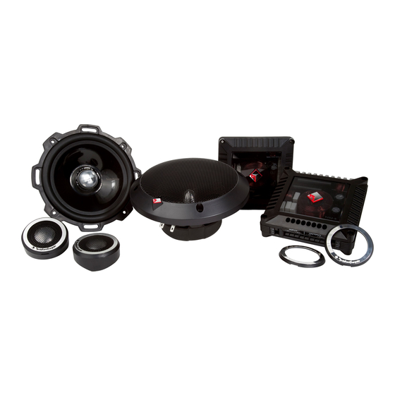
• (1) Set T2 Series Speakers with Tweeters and 2-Way Crossover
or (1) Set T2 Series Tweeters with HP Crossover
• (1) Set of grilles/trim rings
• (2) Sets of tweeter trim rings:
(1 set of polished aluminum)
(1 set of brushed aluminum)
• Tweeter Mounting Hardware with Surface, Angle, and Flush Mounts
• (1) Set Adapter Plates: T252-S (5"x7"/6"x9"), T2652-S (5"x7"/6"x9")
I
NSTALLATION
Before beginning any installation, follow these simple rules:
1.
Be sure to carefully read and understand the instructions before attempting to
install these speakers.
2.
For safety, disconnect the negative lead from the battery prior to beginning the
installation.
3.
For easier assembly, we suggest you run all wires prior to mounting your speakers
in place.
4.
Use high quality connectors for a reliable installation and to minimize signal or
power loss.
5.
Think before you drill! Be careful not to cut or drill into gas tanks, fuel lines,
brake or hydraulic lines, vacuum lines or electrical wiring when working on any
vehicle. If installation in a boat, take care not to cut or drill through the main hull.
6.
Never run wires underneath the vehicle. Running the wires inside the vehicle or
hull area provides the best protection.
7.
Avoid running wires over or through sharp edges. Use rubber or plastic
grommets to protect any wires routed through metal, especially the firewall.
1.
Determine where the speakers will be mounted. Ensure an area large enough for
the speaker to mount evenly. Be sure that the mounting location is deep enough
for the speaker to fit; if mounting in a door, operate all functions (windows, locks,
etc.) through their entire operating range to ensure there is no obstruction.
2.
Refer to the specification chart to determine the proper diameter hole to cut
for your speaker model.The template provided also gives the proper cutout size.
3.
Mark the locations for the mounting screws. Drill the holes with a 1/8" bit.
4.
Feed the speaker wires through the cutout and connect to the speaker terminals.
Be sure to observe proper polarity when connecting the wires.The speaker's
positive terminal is indicated with a "+".
5.
On models with slotted holes, fit the speaker into the cutout and install the
screws in the slots at the top and bottom.This will allow you to rotate the speak-
er to match the remaining mounting holes.When aligned, tighten the screws.
6.
Tighten the screws until the speaker is snug in place to prevent rattling. Do not
over tighten the screws.
NOTE: If needed, use the adapter plate provided to mount the speaker.
See Adapter Plate Templates at the end of this manual.
S
AFETY
C
ONTENTS
C
ONSIDERATIONS
M
OUNTING
T252-S Only
Removing tabs for
some installations
Use pliers to break off
plastic tab.
Example of Discreet Dual Clamp (DDC™)
Tweeter Mounting (Flush Mount)
2
Break off
mounting tab.
snap!
Position to
Align Holes
Cutout
Hole
Example of standard
door installation
Use tip of a small flat
screwdriver to remove tweeter
Panel
Advertisement

Related Manuals for Rockford Fosgate power T2652-S


Summary of Contents for Rockford Fosgate power T2652-S
- Page 1 • (2) Sets of tweeter trim rings: (1 set of polished aluminum) (1 set of brushed aluminum) • Tweeter Mounting Hardware with Surface, Angle, and Flush Mounts • (1) Set Adapter Plates: T252-S (5”x7”/6”x9”), T2652-S (5”x7”/6”x9”) Example of standard NSTALLATION ONSIDERATIONS...
- Page 2 EATURES PECIFICATIONS T252-S T2652-S T2T-S T2 Components Discreet Dual Clamp (DDC™) Nominal Diameter - inch (mm) 5.25 (133) 6.5 (165) 1.0 (25.4) Tweeter Mount Description Component System Component System Tweeter System Every aspect of the new Tweeter design has been...
- Page 3 -2dB -2dB Tweeter Attenuation Switch T252-S & T2652-S Bi-Amp Cossover Wiring Use illustration for proper connection and be sure to maintain speaker polarity. Remove 4 screws from crossover bottom to detatch cover. When BI-AMP switched OFF for one amplifier, use only “TWT” input.
-
Page 4: Specifications
4.80" (122mm) 5.59" (122mm) 5.59" (142mm) (142mm) 4.57" 4.57" (116mm) (116mm) 4.09" 4.09" (104mm) (104mm) Tweeter Tweeter T252-S & T2652-S T252-S & T2652-S 2.10" 0.30" Component Crossover 2.10" 0.30" (53mm) (8mm) Component Crossover (53mm) (8mm) 4.57" 4.57" (116mm) (116mm) 4.09"... - Page 5 Usa illustrazione per la corretta connessione ed essere certi di mantenere la polarità dei diffusori. T252-S & T2652-S Bi-Amp Cossover de cableado 4 Rimuovere le viti dal fondo di crossover detatch copertina. Utilice la ilustración para la correcta conexión y asegúrese de mantener la polaridad de los altavoces.
- Page 6 Remove Shaded Area From Adapter Plate for T252-S Shallow Mount Spacer Plate Adapter Plate Template 6.5" Hole Mounting Remove Shaded Areas Mounting for T252-S 5.25"...
- Page 7 Adapter Plate Template – 6"x9" Hole Mounting For 5"x7" Hole Mounting - Remove Dark Shaded Areas Mounting for T252-S 5.25" Remove For Tweeter Remove Shaded Areas to Mount T2652-S 6.5"...
- Page 8 T252-S Component System Tweeter 1.75" (44mm) Mounting Template T252 Midrange Mounting Holes 5.43" (138mm) T252 Midrange Hole Cutout 4.81" (122mm) Verify Scale Before Using 1.00" (25mm) Template 1.00" (25mm)
- Page 9 T2652-S Component System Tweeter 1.75" (44mm) Mounting Template T2652 Midrange Mounting Holes 6.18" (157mm) T2652 Midrange Hole Cutout 5.57" (141mm) Verify Scale Before Using 1.00" (25mm) Template 1.00" (25mm)
Need help?
Do you have a question about the power T2652-S and is the answer not in the manual?
Questions and answers