
Related Manuals for Chromalox SRM/E


Summary of Contents for Chromalox SRM/E
- Page 1 Installation Instructions Industrial Heating Cable Products PJ438-26 161-057884-010 May, 2021...
-
Page 2: Table Of Contents
Table of Contents Important Safeguards and Warnings ..................3 System Components ....................... 4 Chromalox Cable Types ......................5 General Information ........................ 6 Use of Manual ........................6 Storage ..........................6 Important Installation Notes ....................6 Installation ..........................7 Pre-Installation Guidelines ....................7 Installation Guide: Single Run of Cable ................ -
Page 3: Important Safeguards And Warnings
Do not attempt to the safety of the installation is responsibility of repair damaged heating cable. the user, Chromalox will be glad to assist in mak- • Never energize the cable when it is coiled or on a ing equipment recommendations reel. -
Page 4: System Components
System Components A complete electric heat trace system includes the follow- 3. Controls ing system components – See the figure below for a typical A. Thermostats system. B. Digital Thermostats C. Single/Dual Loop Panels D. Weather Trace Panels 1. Electric Heat Tracing (Self-regulating, Constant Wattage) E. -
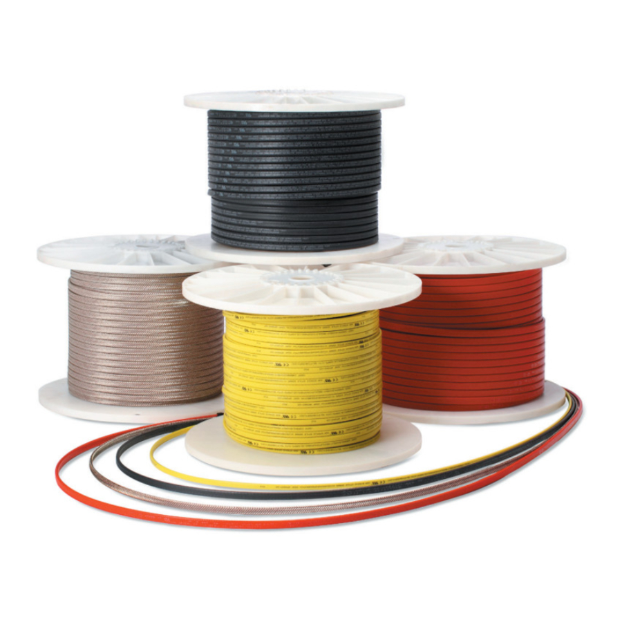
Page 5: Chromalox Cable Types
Twin (Shown) or Single Fluoropolymer Jacket Resistance Wires High Temperature Mineral Insulated SLL Long Line Fluoropolymer Core Matrix Approvals Chromalox heating cables and components approved for use in hazardous and nonhazardous locations. Refer to the spe- cific product data sheets for details. -
Page 6: General Information
They should be stored in a clean location, where they dations. Installation details apply for plastic pipe only are protected from mechanical damage. when Type SRL heating cable is used. Consult factory for applications involving other products. Storage temperature range: 0°F(-18°C) to 140°F(60°C). -
Page 7: Installation
20 megohms familiarize yourself with the products. Complete the following before installation should not be installed. Contact pre-installation steps: your local Chromalox representative. • Verify that the selection of heating cable type and rating •... -
Page 8: Installation Guide: Single Run Of Cable
Installation Guide: Single Run of Cable If installing a single run of heating cable on a pipe, follow the 5. At a heat sink (pipe supports, valves, pumps, reducers, steps below: gauges, bucket strainers, etc.), attach the heater cable to the pipe just before the heat sink. Refer to the design 1. -
Page 9: Installation Guide: Multiple Cable Runs
Installation Guide: Multiple Cable Runs There are two cases where you will need to install more than one heater cable on a pipe: b. Begin pulling the cable off the reel in a large loop down • When the design calls for more than one cable. the piping run. -
Page 10: Installation On Fire Protection Systems
Series of certified cable connection kits as supplied by • The certified minimum cable exposure temperature for Chromalox, Inc. These are only to be used for the opera- SRL and SRM/E cable is -60˚C (-76˚F). tions for which they were designed. -
Page 11: Other Installation Considerations
The minimum bending radius for all When using a pipe hanger, ensure that the heating cable is Chromalox heating cables is six times the minor diameter. not pinched between the pipe and the hanger. Damage to the cable can result in electrical arcing, arc faults, and arc flashes. -
Page 12: Typical Installation Details
Table 3 – Additional Cable Lengths Required for In-Line Components (Based on Iron Pipe Size) Globe Butterfly Shoe Hanger Sleeper Flange Piping Size Gate Valve Valve Ball Valve Valve Support Support Support Pair Dimensions in Feet (Ft.) 1/2 in. 1.00 1.00 1.00 1.00... - Page 13 AD3 - One Cable-Spiralling Method AD4 - One Run of Cable at Pipe Elbow AD5 - Orifice Flange AD6 - Expansion Joint AD7 - Welded Support AD8 - Shoe Support...
- Page 14 AD9 - Valve AD10 - Pressure Gauge AD11 - Diaphragm Pressure Gauge AD12 - Level Gauge AD13 - U Series Power Connection AD14 - U Series Splice & Tee Connection...
- Page 15 SOLIDWORKS Educational Product. For Instructional Use Only. AD16- DL Series Below Insulation End Seal AD15 - EL Series Splice and Tee Kit AD16-2 U Series Above Insulation End Seal AD17 - DL Series Power Connection SOLIDWORKS Educational Product. For Instructional Use Only. AD18 - DL Series Splice &...
-
Page 16: Wiring
(30 mA EPD) thermal breakers are recom- • Selection of installation accessories should be in accor- mended with types SRL, SRP, SRM/E, SLL, and CWM. dance with ChromaTrace 4 design software program. En- • The temperature control should be mounted in a location... - Page 17 Table 4 – Minimum Insulation Resistance Readings Installation Installation Delivery Pre-Insulation Post-Insulation Maintenance 5 MΩ 5 MΩ Chromalox SRL 20 MΩ 20 MΩ 5 MΩ 5 MΩ Chromalox SRP 20 MΩ 20 MΩ 5 MΩ 5 MΩ...
-
Page 18: Heating Cable Components
Heating Cable Components Connection Kits Table 5 – U Series Connection Kits Overview Installation Catalog Number Description Manual NEMA 4X rated junction box designed to connect cables to customer supplied power wiring. This kit provides water-resistant cable entry for one cable, enclosure support, terminal block, and a water-resistant corrosion-resistant wiring enclo- Power Connection... - Page 19 3” or more, and one for smaller pipes PJ450 End Seal Kit NEMA 4X rated junction box that provides water- proof cable entry for up to three (3) cables with an opening to accept a 3/4” conduit hub (Chromalox RTPC CCH-2 or equal). Power Connection PJ451...
- Page 20 Table 8 – HL Series Connection Kit Overview Installation Catalog Number Description Manual Division 1 certified junction box and seal fitting. The kit is designed to connect self- regulating cables to customer supplied HL-PC power wiring. The pipe stand-off and seal Power Connection PJ912 Box for Hazardous...
- Page 21 Table 9 – MI Series Connection Kit Overview Installation Catalog Number Description Manual NEMA 7 cast aluminum junction box for miner- al insulated cable. JB-7-4 MI Cable Power Connection Kit Pipe mounting bracket to be used with the JB-7-4 power connection kit. JB-7-MB MI Cable Pipe Mounting Bracket...
-
Page 22: Accessories
Accessories Table 10 – Accessories Overview Installation Catalog Number Description Manual 180 ft roll of aluminum foil installation tape. 2-mil thickness with high tensile strength; AT-1 2-1/2” wide. 200°F (93°C) rating. Minimum Aluminum Tape application temperatures 40°F (5°C). 66 ft roll of glass cloth installation tape. 3/8” wide. -
Page 23: Control Systems
Control Systems Ambient Sensing The ambient sensing control systems activate the heating cable when the ambient temperature falls below the thermostat set point. It is important that these devices are installed above ground at the pipe segment that is subject to the lowest tempera- tures and fastest wind speeds. - Page 24 Line Sensing The line sensing control systems activate the heating cable when the pipe temperature drops below the desired setpoint. The sensor must be secured to the pipe with aluminum tape and the insulation must be sealed where the capillary comes through. The device should be mounted above ground in an area without heavy pedestrian or equipment traffic.
- Page 25 Table 16 – Thermostats with Power Connection Installation Catalog Number Description Manual NEMA 4X rated junction box designed to connect a single cable run to power and control cable output via pipe temperature in non-hazardous areas. This Line Sensing kit provides water-resistant cable entry with a 3/4” Thermostat and PJ942 opening to accept a conduit hub (CCH-2 or equal).
-
Page 26: Controllers
PK497 NEMA 4X 305SS enclosure. Fully integrated package that consolidates up to 252 temperature sensor signals in a single enclosure. Works seamlessly with the Chromalox IntelliTrace ITLS/ IntelliTrace Remote ITAS heat trace control panels. Sensor Panel The DTS-HAZ digital thermostat is a NEMA 4X... - Page 27 Table 18 – Controllers Comparison DTS-HAZ ITAS ITLS ITASC1D2 ITLSC1D2 FPAS FPASM FPLS FPLSM Controls Ambient • • • • • • sensing Line sensing • • • • • • PASC • • • • • Monitoring Ambient • •...
-
Page 28: Thermal Insulation
Thermal Insulation • Insulation must be covered by a weatherproof barrier, An installed heating circuit should be thermally insulated im- mediately to provide protection from damage from ongoing such as an aluminum jacket. work. Things to remember about insulating: • If you are using metal jacketing and sheet metal screws, •... -
Page 29: Specifications
Temperatures (˚F) Output (W/Ft.) 10.1 10.6 w/o AT-1 Tape w AT-1 Tape Table 20 – SRL Circuit Breaker Selection (Max. Circuit Lengths in Ft.) 50˚F Start-up (Ft.) 0˚F Start-up (Ft.) -20˚F Start-up (Ft.) Cable Rating 10A 15A 20A 25A 30A 40A 10A 15A 20A 25A 30A 40A 10A 15A 20A 25A 30A 40A... - Page 30 Table 25 – Commercial Heating Device Installation Type Intallation Type Type Definition Examples of Type Cable Type Hot water lines Freeze protection SRL, SRP, Sprinkler systems Grease lines Insulated Surfaces SRM/E (Including Pipe) Pre-insulated pipe Fuel oil lines CWM, MI...
-
Page 31: Troubleshooting
Contact a Chromalox representative and modify Error in thermal design design as needed. Apply voltage as specified. Check/repair electrical Incorrect voltage applied supply lines. -
Page 32: Locating Faults
When testing any Chromalox heat trace product, al- Example: There is a bus wire short at an unknown point on ways utilize the proper protective equipment and be a 100ft cable. - Page 33 Capacitance Test The capacitance test can be used to estimate the length of Example: A heating cable with a capacitance factor of 7 ft/ an intact heating cable or the fault location of a severed cable nF is severed at an unknown point. The capacitance reading that has passed the insulation resistance testing.
-
Page 34: Insulation Resistance (Megger) Test
Ensure the meter has an auto-range up to 100A. If For additional information about this test, please watch the possible, the meter should be battery-operated, though digi- “End of Current Voltage Test” video in the Chromalox video tal or analog meters can also be used. library: https://www.chromalox.com/en/Resources-and-Support/... -
Page 35: Installation And Maintenance Log
Installation and Maintenance Log Reference Information Circuit Number Circuit Breaker Number Drawing Number Circuit Length Heat Tracing Visual Checks Initial No Signs of Moisture, Corrosion or Damage Date Initial Proper Electrical Connection Date Initial Proper Grounding of the Braid Date Heat Tracing Electrical Checks Meg Ohms Megger Test (500 VDC) - Page 36 Limited Warranty: Please refer to the Chromalox limited warranty applicable to this product at http://www.chromalox.com/customer-service/policies/termsofsale.aspx. Chromalox, Inc. 1347 Heil Quaker Boulevard Lavergne, TN 37086 (615) 793-3900 www.chromalox.com © 2021 Chromalox, Inc.
Need help?
Do you have a question about the SRM/E and is the answer not in the manual?
Questions and answers