Table of Contents
Advertisement
Quick Links
RTPC Power Connection Kit for Self-Regulating
and Constant Wattage Rapid-Trace Heating Cable
ELECTRIC SHOCK HAZARD. Disconnect all power
before installing or servicing heating cable and
accessories. A qualified person must perform
Installation and service of heating cable and
accessories. Heating cable must be effectively
g r o u n d e d i n a c c o r d a n c e w i t h t h e N a t i o n a l
Electrical Code. Failure to comply can result in
personal injury or property damage.
NOTE: All electrical wiring, including GFCI (Ground Fault
Circuit Interrupters), must be done according to National
Electrical or local codes by a qualified person.
The RTPC Kit is used to connect base, braided (-C) and over-
coated (-CR or -CT) versions of Self-Regulating and Fluoropolymer
insulated Constant Wattage Rapid-Trace Heating Cables to power.
© 2010 Chromalox, Inc.
Chromalox
Installation Instructions
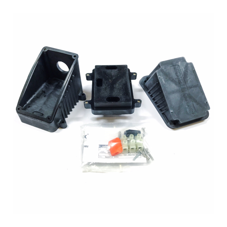
RTPC Power Connection Kit Parts:
1 - Molded Junction Box consisting of:
Base - Box - Lid - Hardware
1 - Three Position Terminal Block
1 - Mounting Screw for Terminal Block
®
SERVICE REFERENCE
DIVISION
SALES
REFERENCE
DATE
1 - Black Cable Grommet
1 - Orange Cable Grommet
1 - Cover Gasket
GENERAL
The cable grommet is furnished with this kit, such that the black
grommet is used for self-regulating cables SRL, SRF, SRM/E,
SRL/S, SRMF/S and the orange grommet is used for constant
wattage cable CWM and self-regulating cable SRS.
Each kit contains enough material to make one power connec-
tion point. It is possible to connect up to three Self-Regulating or
two Constant Wattage Cables in the same box. (One grommet
required for each cable.)
Materials required for installation include: standard electrical
cutters, screwdriver, sharp utility knife and a pipe strap
(Chromalox PS or equal).
Wipe inside lip of cover with a clean cloth. Remove protective
backing from the gasket and affix it to the cover lip. Press firmly
all around for proper adhesion.
4
RT
SECTION
(Supersedes PJ451-10)
161-562762-001
MARCH, 2009
PJ451-11
Advertisement
Table of Contents

Related Manuals for Chromalox RTPC


Summary of Contents for Chromalox RTPC
- Page 1 Electrical or local codes by a qualified person. all around for proper adhesion. The RTPC Kit is used to connect base, braided (-C) and over- coated (-CR or -CT) versions of Self-Regulating and Fluoropolymer insulated Constant Wattage Rapid-Trace Heating Cables to power.
- Page 2 INSTALLATION NOTE: These instructions are for all Self-Regulating and Constant Wattage heating cables in ordinary locations. Consult factory for installation of braided cable in hazardous locations. Not all instructions are for all cables. Each step of the instructions will have a heading in boldface stating what type of cable each instruction is intended for.
- Page 3 See Figure 9. 3/8” Figure 12 3/4” 13. FOR ALL CABLES: Connect conduit hub (Chromalox CCH or equal) to the box. Attach conduit to hub and bring power leads into box. See Figure 13. Figure 9 10. FOR CONSTANT WATTAGE CABLES: Score the outer jacket 3/4 inch from the end of the cable and remove the jacket.
- Page 4 Carefully push the wires into the box. Secure the lid to box. See Figure 16. Limited Warranty: Please refer to the Chromalox limited warranty applicable to this product at http://www.chromalox.com/customer-service/policies/termsofsale.aspx. 1347 HEIL QUAKER BLVD., LAVERGNE, TN 37086 Phone: (615) 793-3900...
Need help?
Do you have a question about the RTPC and is the answer not in the manual?
Questions and answers