Summarization of Contents
1 Introduction
1.1 Overview
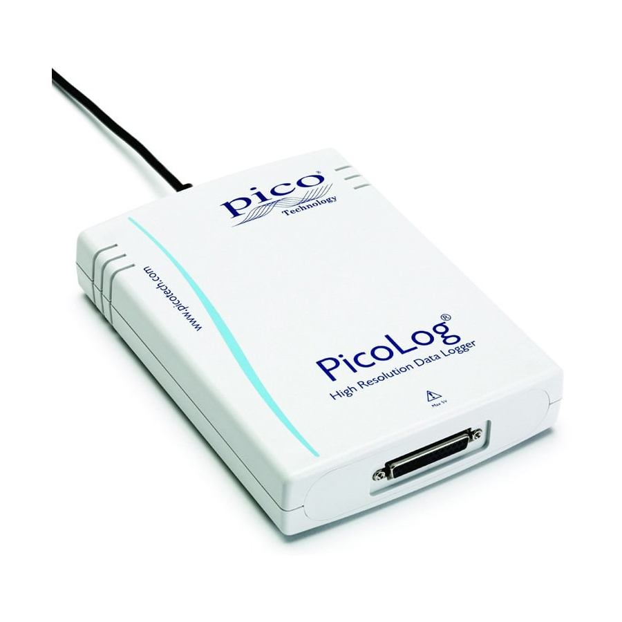
Provides a general introduction to the ADC-20/ADC-24 data loggers and their package contents.
2 Notices
2.1 Safety warning
Details crucial safety precautions for operating the data loggers to prevent damage or injury.
2.2 Legal information
Outlines the licensing terms, usage restrictions, copyright, and liability for the software.
2.3 CE notice
States compliance with European directives and standards for electromagnetic compatibility and safety.
2.4 FCC notice
Reports compliance with FCC rules for digital devices, addressing potential radio frequency interference.
2.5 Trademarks
Lists registered trademarks associated with Pico Technology and Microsoft products.
2.6 Updates
Explains how to obtain software upgrades and the vendor's right to charge for physical media.
2.7 Support and refunds
Provides contact information for technical support and details the process for product returns and refunds.
3 Getting started
3.1 Installing the software
Guides users through the process of installing the necessary software and drivers for the data logger.
3.2 Connecting the data logger
Instructs on how to physically connect the data logger to the computer via USB.
3.3 Starting PicoLog
Details the steps to launch the PicoLog application and begin configuration for data logging.
4 About the unit
4.1 Introduction
Offers a high-level overview of the ADC-20/ADC-24 data loggers, highlighting their features.
4.2 Specifications
Presents detailed technical specifications for the ADC-20 and ADC-24 data loggers in tabular format.
4.3 Analog connector
Describes the pinout and function of the DB25 analog connector for input signals.
4.4 Noise-free resolution and conversion time
Explains noise-free resolution and provides a table correlating conversion time with resolution.
4.5 ADC-20/ADC-24 terminal board
Recommends and describes the optional terminal board for easier connection of signals.
4.6 LED
Explains the function of the LED indicator on the data logger for status verification.
5 Programmer's reference
5.1 Recording methods
Outlines three different methods for recording data: streaming, single value (blocking/non-blocking).
5.2 Windows driver
Introduces the DLL driver for programming the data logger from Windows applications.
5.3 Scaling
Explains how to convert raw ADC values to voltage readings using driver functions.
5.4 Driver functions
Lists and briefly describes the available API functions for controlling the data logger.
5.4.1 HRDLCloseUnit
Shuts down a data logger unit, releasing resources.
5.4.2 HRDLCollectSingleValueAsync
Starts sampling one value asynchronously without blocking the application.
5.4.3 HRDLGetMinMaxAdcCounts
Retrieves the minimum and maximum ADC counts available for a device.
5.4.4 HRDLGetNumberOfEnabledChannels
Returns the number of analog channels currently enabled on the unit.
5.4.5 HRDLGetSingleValue
Takes one sample for a specified channel at selected range and time.
5.4.6 HRDLGetSingleValueAsync
Retrieves a sample previously initiated by HRDLCollectSingleValueAsync.
5.4.7 HRDLGetTimesAndValues
Returns requested samples and their timestamps for enabled channels.
5.4.8 HRDLGetUnitInfo
Writes unit information, including error codes, to a character string.
5.4.9 HRDLGetValues
Returns requested samples for each enabled channel.
5.4.10 HRDLOpenUnit
Opens a data logger unit, returning a handle for subsequent operations.
5.4.11 HRDLOpenUnitAsync
Opens a data logger unit asynchronously without blocking the thread.
5.4.12 HRDLOpenUnitProgress
Checks the progress of an asynchronous unit opening operation.
5.4.13 HRDLReady
Indicates if readings are ready to be retrieved from the driver.
5.4.14 HRDLRun
Starts the device sampling and storing samples into the driver's buffer.
5.4.15 HRDLSetAnalogInChannel
Enables or disables a selected analog channel and sets its voltage range.
5.4.16 HRDLSetDigitallOChannel (ADC-24 only)
Configures digital input/output channels for the ADC-24 device.
5.4.17 HRDLSetInterval
Sets the sampling time interval for data collection.
5.4.18 HRDLSetMains
Configures mains noise rejection settings (50 Hz or 60 Hz).
5.4.19 HRDLStop
Stops the device from sampling data.
5.5 Programming examples
Provides information on accessing programming examples included with the SDK.
5.6 Sequence of calls and data flow
Illustrates typical sequences of API calls for different recording methods.
5.6.1 Streaming recording methods
Details how to collect data in blocks or continuous streams.
5.6.1.1 Collecting a block of data
Describes the process for collecting a single block of data and then stopping.
5.6.1.2 Collecting windowed or streaming data
Explains methods for collecting data in windowed or streaming modes.
5.6.2 Single-value recording methods
Explains how to collect single readings using blocking or non-blocking methods.
5.6.2.1 Collecting a single reading, blocking
Describes collecting a single reading that blocks the calling thread.
5.6.2.2 Collecting a single reading, non-blocking
Describes collecting a single reading without blocking the calling thread.


Need help?
Do you have a question about the ADC-24 and is the answer not in the manual?
Questions and answers