
Related Manuals for pico Technology USB DrDAQ


Summary of Contents for pico Technology USB DrDAQ
- Page 1 USB Dr.DAQ Data Logger User's Guide usbdrdaq.en r4 Copyright © 2013 Pico Technology Ltd. All rights reserved.
-
Page 3: Table Of Contents
4 Examples of digital output use ..................................30 5 USB DrDAQ scaling files (.DDS) ..................................32 6 Calibration 3 Software updates ............................34 4 Glossary ............................35 5 Appendix A: Declaration of Conformity ............................36 ............................37 Index Copyright © 2013 Pico Technology Ltd. All rights reserved. usbdrdaq.en r4... -
Page 5: Introduction
±30 V may cause permanent damage to the unit. Your own sensors should draw no more than 100 mA from the 5 V. The USB DrDAQ is not limited or protected so overcurrents or short circuits could cause damage to the PC USB port. -
Page 6: Legal Information
Liability. Pico Technology and its agents shall not be liable for any loss, damage or injury, howsoever caused, related to the use of Pico Technology equipment or software, unless excluded by statute. -
Page 7: Product Information
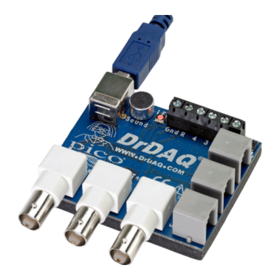
USB DrDAQ User's Guide Product information Welcome Thank you for buying a USB DrDAQ data logger from Pico Technology! This low-cost measuring device is supplied ready to use with all cables, software and examples. Features include: Built-in sensors for light, sound (level and waveforms) and temperature... -
Page 8: Using Picoscope And Picolog
"Install Software" link and follow the on-screen instructions. 2. Plug in the USB DrDAQ device. Windows will recognise it and prepare your computer to work with it. Wait until Windows tells you that the device is ready to use. -
Page 9: Getting Started With Picoscope
The green Start button will be highlighted to show that PicoScope is ready. Adjacent to this is the red Stop button. 3. Try clicking your fingers over the microphone, and the trace on the screen should react. USB DrDAQ is now successfully installed and working. A typical 'finger click' trace... -
Page 10: Displaying Channels
In this example, we have added Temp. While the trace is running, put your finger on the temperature sensor and notice the corresponding rise on the screen. usbdrdaq.en r4 Copyright © 2013 Pico Technology Ltd. All rights reserved. -
Page 11: Changing The Oscilloscope Timebase
2.6.3 Changing the oscilloscope timebase The timebase can be adjusted by selecting the drop-down menu shown below. Change the timebase to 50 ms/div to change the display as follows: Copyright © 2013 Pico Technology Ltd. All rights reserved. usbdrdaq.en r4... -
Page 12: Using The Trigger
2.6.5 Adding spectrum views So far we have looked at the oscilloscope functions. PicoScope allows USB DrDAQ to be used as a spectrum analyzer as well. The buttons on the top left-hand side control the oscilloscope and spectrum views. -
Page 13: Adjusting The Rgb Led
When Enable LED Control is active, the LED will not flash when sampling. The USB DrDAQ units include an RGB LED. The colour of this LED can be changed by clicking the LED icon above the oscilloscope window. The following drop down will... -
Page 14: Controlling The Digital Outputs
The USB DrDAQ device includes several digital connections. To activate the digital outputs, ensure your accessory is connected both to the GND of the USB DrDAQ and the digital connection you wish to control. To operate the connections click the digital output icon above the oscilloscope window. -
Page 15: Specifications And Connections
0 to 1.5 V running up to amplitude. 2 MS/s ±1.5 V offset. 2 mV *PicoScope supports digital output only, while PicoLog and the SDK support digital input and output. Copyright © 2013 Pico Technology Ltd. All rights reserved. usbdrdaq.en r4... -
Page 16: Connections
Power up to 100 mA @ 5V (not protected/limited) Refer to Making your own sensors for further information. When used as basic voltage or resistance inputs, the External connections support sampling rates up to 1 kS/s. usbdrdaq.en r4 Copyright © 2013 Pico Technology Ltd. All rights reserved. -
Page 17: Channel Scaling
2.9.1 Overview As well as the built in sensors, USB DrDAQ has sockets for optional external sensors. When a sensor is plugged in to the external sensor sockets, the software detects it and automatically scales readings. For example, if a temperature sensor is plugged in, readings are displayed in °C, or if a humidity sensor is plugged in, readings are... -
Page 18: Dd011 Ph Electrode
Replacement electrodes are available from Pico Technology. If you suspect that the pH input on USB DrDAQ may be defective, then short out the BNC connector using a terminator plug. The reading on the screen should be pH 7. If it is not, the most likely reason is that someone has calibrated the probe incorrectly. - Page 19 25 C. A container of clean water is also required to wash the electrode between buffers. 1. Connect the pH electrode to USB DrDAQ and display the pH using either PicoScope or PicoLog (depending on which program you are calibrating for).
-
Page 20: Pp066 Reed Switch
You may use the unit to connect a simple, single-pole switch (such as a micro-switch) to USB DrDAQ. You will need to obtain a switch and some insulated connecting wire. Remember to keep magnets or magnetic fields away from the unit when you use it with an external switch. -
Page 21: Dd101 Humidity Sensor
Do not allow the DD101 sensor to become wet. The DD101 is a non- condensing sensor and liquid (including condensation) inside the case may damage it. The DD101 may be connected to either Ext 1, Ext 2 or Ext 3 on USB DrDAQ. Tips for use of DD101 Humidity Sensors The sensor responds to humidity changes more slowly in still air. - Page 22 Calibration of the sensor involves: Preparation of the calibration equipment. Measurement of the standard saturated solutions. Creation of calibration data for the USB DrDAQ software. A check that the calibrated sensor is accurate. Note: You must measure at least two different standard solutions to provide two or more fixed points for calibration.
- Page 23 Always use fresh solutions to ensure that the chemicals have not become contaminated or degraded. Allow the standard solutions and other equipment to reach the same temperature (ideally 20 C) before you start. Copyright © 2013 Pico Technology Ltd. All rights reserved. usbdrdaq.en r4...
- Page 24 Connect the DD101 and DD100 sensors to USB DrDAQ. Take your measurements Start the PicoLog Recorder software for USB DrDAQ. Make sure USB DrDAQ is receiving readings from the sensors on Ext 1 or Ext 2. Seal the test container and close the insulated box. If you are using a fan, start the fan.
- Page 25 Click OK to close the Edit DrDAQ Measurements dialog. The Edit DrDAQ Measurements dialog closes. Click OK to close the DrDAQ Measurements dialog. The DrDAQ Measurements dialog closes. This completes the entry of the calibration data. Copyright © 2013 Pico Technology Ltd. All rights reserved. usbdrdaq.en r4...
-
Page 26: Dd103 Oxygen Sensor
2.9.6 DD103 Oxygen Sensor The DD103 Oxygen Sensor is used to measure the percentage of oxygen in a gas. The sensor plugs into the external sensor sockets of USB DrDAQ using the supplied cable. Specification Sensor Type Galvanic Cell (lead-oxygen with weak acid electrolyte) - Page 27 USB DrDAQ User's Guide If you have not yet set up USB DrDAQ with PicoLog, do so using the PicoLog help file before continuing below: 1. Connect the Oxygen Sensor to the socket labelled Ext1 on the USB DrDAQ unit.
-
Page 28: Making Your Own Sensors
2.10 Making your own sensors 2.10.1 Overview Making your own sensors for USB DrDAQ is quite straightforward provided that you follow these guidelines. Your own sensors should draw no more than 100 mA from the 5 V. The USB DrDAQ is not limited or protected so overcurrents or shorts could cause damage to the PC USB port. -
Page 29: Powering The Sensor
The Signal Input channel has 100 kΩ pull-up resistors to 2.5 V, so that the input can be either a resistance or a voltage. Here is a block diagram of a typical USB DrDAQ sensor: 1 = Signal input 2 = Ground... -
Page 30: Scaling
There are many factors to take into account when designing scaling circuitry: Sensitivity The USB DrDAQ has 12-bit resolution over the 0 to 2.5 V input range. This means the sensitivity is: 2500 mV / 2^12 = 0.611 mV To make the most of the resolution, the signal output from the sensor should use as much of the input range of the USB DrDAQ as possible. - Page 31 It is quite usual to see offsets in output signals from sensors. Sensor output The USB DrDAQ requires an input signal in DC volts or resistance. The sensor in question could give an output in other units such as resistance, current or AC volts. Drift It is possible that the sensor output drifts over time.
- Page 32 For relatively small currents a simple shunt resistor can be used to convert the current into voltage which the DrDAQ can then measure. A suitable resistor (R) for the USB DrDAQ is 120 ohms. This would give (using Ohm's Law): 0.4 volts at 4 mA...
-
Page 33: Examples Of Digital Output Use
USB DrDAQ using the Mask and Alarm functions of PicoScope. With USB DrDAQ connected and PicoScope open: Connect the LED to the GND connection on the USB DrDAQ and digital connection 2 (refer to Connections). Note: Any digital connection can be used but we are using 2 in this example). -
Page 34: Usb Drdaq Scaling Files (.Dds)
A unique number, from 1 to 99, to identify this entry. (Pico-created numbers are from 100 upwards). Resistor=1 The ID resistor value in kiloohms. In this example " " represents 1k, " " represents 2k2 and so on. usbdrdaq.en r4 Copyright © 2013 Pico Technology Ltd. All rights reserved. - Page 35 1100 Light 1000 LongName=Temperature Used in PicoLog ShortName=TempC This field is not used by USB DrDAQ running PicoScope or PicoLog. Units=C Displayed on graphs MinValue=-40 MaxValue=120 Note: For PicoScope these values will determine the maximum and minimum values displayed in Oscilloscope View. For PicoLog these values determine what Maximum range is displayed in the Graph View (set in the Graph Options dialog).
-
Page 36: Calibration
Single-Point Calibration. This only occurs in one circumstance: One pair of values is known - for example on the USB DrDAQ oxygen sensor. The sensor is known to output 0 mV at 0% oxygen content. Therefore we only need to find one other pair of values. - Page 37 Both PicoLog and PicoScope have the facility to manually enter look-up tables (see the respective help files). You can also make a more permanent reusable scaling table with USB DrDAQ Scaling Files (.DDS) Copyright © 2013 Pico Technology Ltd. All rights reserved. usbdrdaq.en r4...
-
Page 38: Software Updates
The latest versions of PicoScope can check for updates automatically and will advise you if an update is available. The latest version of all our software can be downloaded free of charge from the Pico Technology web site at http:// www.picotech.com/. -
Page 39: Glossary
USB. Universal Serial Bus. This is a standard port used to connect external devices to PCs. The port supports a data transfer rate of up to 12 Mbps with USB DrDAQ. Vertical resolution. A value, in bits, indicating the number of unique values that the oscilloscope can generate when converting input voltages to digital values. -
Page 40: Appendix A: Declaration Of Conformity
Appendix A: Declaration of Conformity Appendix A: Declaration of Conformity usbdrdaq.en r4 Copyright © 2013 Pico Technology Ltd. All rights reserved. -
Page 41: Index
1, 3 9, 10, 29 Legal information USB DrDAQ Making your own sensors Measuring pH Overvoltage protection Oxygen sensor pH electrode PicoLog How to use PicoScope How to use Copyright © 2013 Pico Technology Ltd. All rights reserved. usbdrdaq.en r4... - Page 43 USB DrDAQ User's Guide Copyright © 2013 Pico Technology Ltd. All rights reserved. usbdrdaq.en r4...
- Page 44 Pico Technology James House Colmworth Business Park ST. NEOTS Cambridgeshire PE19 8YP United Kingdom Tel: +44 (0) 1480 396 395 Fax: +44 (0) 1480 396 296 www.drdaq.com usbdrdaq.en r4 17.05.2013 Copyright © 2013 Pico Technology Ltd. All rights reserved.
Need help?
Do you have a question about the USB DrDAQ and is the answer not in the manual?
Questions and answers