Table of Contents
Advertisement
Quick Links
Advertisement
Table of Contents

Related Manuals for ETNA EAR Series


Summary of Contents for ETNA EAR Series
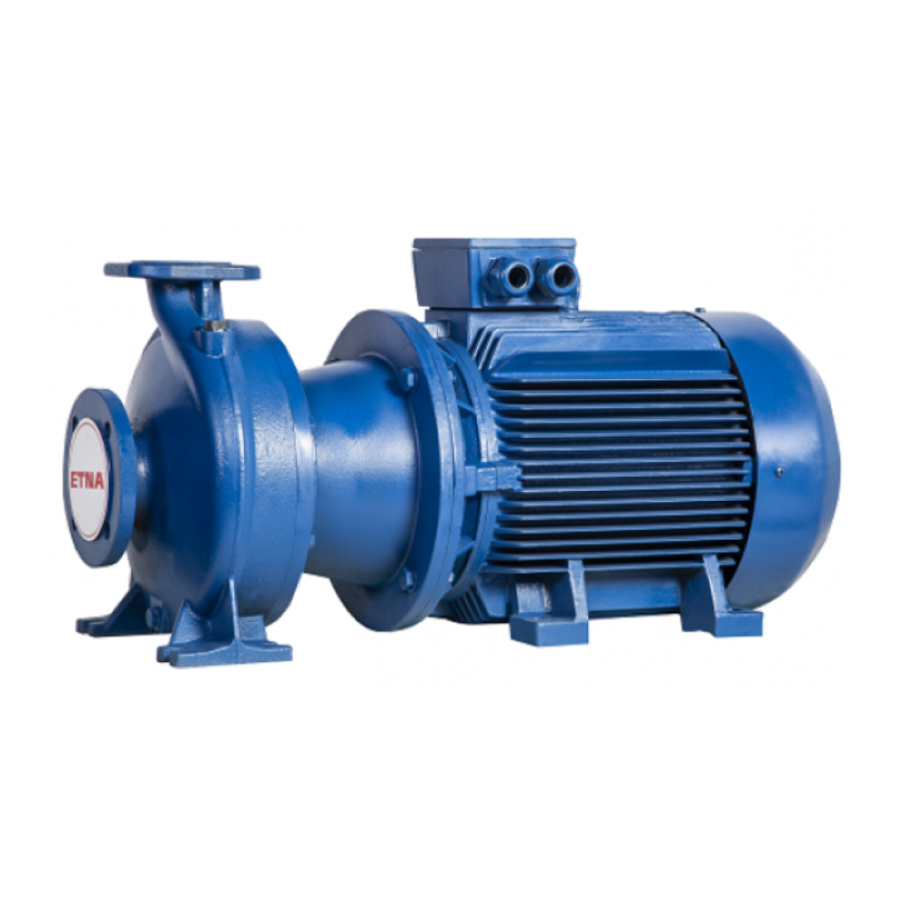
- Page 1 End Suction Pumps Installation, Operation And Maintenance Manual...
-
Page 2: Introduction And Safety
1. INTRODUCTION AND SAFETY 1.1 Introduction The purpose of this manual is to provide necessary information for: • Installation • Operation • Maintenance CAUTION: Read this manual carefully before installing and using the product. Improper use of the product can cause personal injury and damage to property, and may void the warranty. NOTICE: Save this manual for future reference, and keep it readily available at the location of the unit. -
Page 3: Warranty
CAUTION: Always specify the exact product type and part number when requesting technical information or spare parts from the sales department. For more information about the product’s spare parts, visit sales network’s website. www.etna.com.tr... -
Page 4: Transportation And Storage
2. TRANSPORTATION AND STORAGE 2.1 Inspect the Delivery 1. Check the outside of the package for evident signs of damage. 2. Notify our distributor within eight days of the delivery date, if the product bears visible signs of damage. Unpack the unit 1. -
Page 5: Product Description
The product must be stored at an ambient temperature from -5°C to +40°C (23°F to 104°F). 3. PRODUCT DESCRIPTION 3.1 Pump Design The pump is a horizontal pump with volute casing close coupled to standard electric motors. The pump can be used for handling: www.etna.com.tr... - Page 6 • Cold or warm water • Clean liquids • Liquids which are not chemically and mechanically aggressive to the pump materials. The product can be supplied as a pump unit (pump and electric motor) or only as a pump. NOTICE: If you have purchased a pump without motor, make sure that the motor is suitable for coupling to the pump.
-
Page 7: Pump Description
Ductile iron /Bronze Standard 3.6 Mechanical Seal Unbalanced single mechanical seal acc. EN 12756, version K. 3.7 Application Limits Limits of operation The operating limits of the pump unit regarding pressure, temperature, performance and speed are shown in the data sheet. www.etna.com.tr... - Page 8 • Do not exceed the output given on the motor name plate. • Avoid sudden changes in temperature (temperature schoks). • The pump and motor should run evenly and without vibrations; check at least once a week. Maximum number of starts per hour 0.25-3.00 4.00-7.50 11-15 18.5-22...
-
Page 9: Installation
• If possible, place the pump slightly higher than the floor level. • The ambient temperature must be between 0°C (+32°F) and +40°C (+104°F). • The relative humidity of the ambient air must be less than 50% at +40°C (+104°F). • Contact the Sales and Service Department if: www.etna.com.tr... -
Page 10: Piping Requirements
– The relative air humidity conditions exceed the guidelines. – The room temperature exceeds +40°C (+104°F). – The unit is located more than 1000 m (3000 ft) above the sea level. The motor performance may need to be de-rated or replaced with a more powerful motor Pump positions and clearance Provide adequate light and clearance around the pump. -
Page 11: Electrical Requirements
• The electrical leads are protected from high temperature, vibrations, and collisions. • The power supply line is provided with: – A short-circuit protection device – A mains isolator switch with a contact gap of at least 3 mm www.etna.com.tr... - Page 12 The electrical control panel checklist NOTICE: The control panel must match the ratings of the electric pump. Improper combinations could fail to guarantee the protection of the motor. Check that the following requirements are met: • The control panel must protect the motor against overload and short-circuit. •...
- Page 13 • Adequate space between pump or motor shaft must be left depending on the used coupling. • Between pump and base frame must be an adequate shimming, so that in case of replacement the same height between bottom and centerline can be adjusted (recommended vertical adjustment 47-6 mm) www.etna.com.tr...
-
Page 14: Piping Checklist
4.3.2 Piping Checklist Check that the following are adhered to: • The suction lift line has been laid with a rising slope, at positive suction head line with a downward slope towards the pump Fig. 6 page 34. • The nominal diameters of the pipelines are at least equal to the nominal diameters of the pump ports. •... -
Page 15: Electrical Installation
For wiring diagrams, see Figure 11 on page 36. The diagrams are also available on the back of the terminal box cover. a) Connect the ground (earth) lead. Make sure that the ground (earth) lead is longer than the phase leads. b) Connect the phase leads. 3. Mount the terminal box cover. www.etna.com.tr... -
Page 16: Commissioning, Startup, Operation, And Shutdown
NOTICE: Tighten the cable glands carefully to ensure protection against cable slipping and humidity entering the terminal box. 4. If the motor is not equipped with automatic reset thermal protection, then adjust the overload protection according to the list below. –... -
Page 17: Start The Pump
2. Gradually open the on-off valve on the discharge side of the pump. At the expected operating conditions, the pump must run smoothly and quietly. If not, refer to Troubleshooting on page 27-30. 6.MAINTENANCE Precautions Electrical Hazard: Disconnect and lock out electrical power before installing or servicing the unit. www.etna.com.tr... -
Page 18: Motor Bearings
WARNING: • Maintenance and service must be performed by skilled and qualified personnel only. • Observe accident prevention regulations in force. • Use suitable equipment and protection. • Make sure that the drained liquid does not cause damage or injuries. 6.1 Service If the user wishes to schedule regular maintenance deadlines, they are dependent on the type of pumped liquid and on the operating conditions of the pump. -
Page 19: Dismantling And Repair Of Pump
• Loosen screws for support foot from the base frame. • Hang the Back Pull Out Assembly onto a lifting device, so that it won´t sink down or press into the volute casing during the dismounting. Example see picture 1 for lifting recommendations. www.etna.com.tr... - Page 20 • Loosen hexagon head bolt from the casing. • Using the jack belts provided, separate the Back Pull Out Assembly from the casing. 7.4. Removal of the Mech. Seal Use the sectional drawing and data sheet of the mech. seal for this purpose. •...
-
Page 21: Removal Of Impeller
• For further dismounting the Back Pull Out Assembly should be placed in the vertical position (with vertical shaft, see picture 3). Attention: Precautions should be taken to prevent the Back Pull Out Assembly from tipping! Picture 2 www.etna.com.tr... - Page 22 7.7 The Stuffing Box Use the sectional drawing and cover seal chamber for stuffing box. • Remove and disassemble the pump according to the installation, operation and user manual. The stuffing box is the name given to the hole section which houses the seal around the pump shaft preserving the barrier between the inner and outer diameter of the pump shaft or sleeve, while allowing the shaft to turn in the casing in a way that allows movement and prevents leakage.
- Page 23 Making sure your packing rings are properly placed and have adequate space to perform their functions will keep the pump running well. Careful maintenance and quality packing rings will be worthwhile when you extend the life of your pump. www.etna.com.tr...
-
Page 24: Removal Of Bearing
Picture 4 Picture 3 7.8 Removal of Bearing Remove coupling with a coupling puller (picture 4), remove coupling key. Picture 5 • Remove the bearing seal cover-inboard (oil seal) using 2 screw drivers (see pic 5) starting from the inner and outer edges. •... - Page 25 Cover seal chamber Impeller Radial clearances s (mm) Wear ring Picture 6 When the wear limits has been reached or exceeded, the worn parts must be replaced. For wear ring tolerances table see page 39. * Wear rings are optional www.etna.com.tr...
- Page 26 For volute casings with a wear ring and cover seal chambers casings with a wear ring there are the following possibilities to restore the correct clearance: a) Renew impeller and wear ring. Then the original measures are restored. b) A customized wear ring (bored to fit) can be supplied to avoid replacement of the impeller. Please contact factory for details.
-
Page 27: Troubleshooting
Check the: • Liquid level in the tank, or the mains The protective device against dry running pressure. has tripped. • Protective device and its connecting cables. The fuses for the pump or auxiliary circuits Replace the fuses. are blown. www.etna.com.tr... - Page 28 8.3 The Electric Pump Starts, But The Thermal Protector Trips Or The Fuses Blow Immediately After Cause Remedy The power supply cable is damaged. Check the cable and replace as necessary The thermal protection or fuses are not Check the components and replace as suited for the motor current necessary Check the components and replace as...
- Page 29 There is a leakage in one or both of the following components: Repair or replace the faulty component. • The suction pipe • The foot valve or the check valve There is air in the suction pipe. • Bleed the air. www.etna.com.tr...
- Page 30 8.10 The Pump Starts Up Too Frequently Cause Remedy There is a leakage in one or both of the following components: • The suction pipe Repair or replace the faulty component. • The foot valve or the check valve There is a ruptured membrane or no air See the relevant instructions in the pressure pre-charge in the pressure tank.
- Page 31 X = Other 8. Number of poles; 2 = 2–pole, 4 = 4–pole, 6 = 6– pole Cast Iron EN-GJL-250 Ductile Iron GJS-400-15 Cast Iron EN-GJL-200 Bronze CC 380K/B584 Stainless Steel AISI 304 BQ1VGG BQ1EGG Q1Q1VGG Q1Q1EGG U3AEGG U3AVGG www.etna.com.tr...
- Page 32 Packing Seal Material Casing Lower Half Casing Upper Half PACKING DETAIL PUMP Impeller TYPE LENGTH DIAMETER Cover Stuffing Box EA 50/26 131.9 Casing Ring EA 50/32 150.8 Lantern Ring EA 65/26 150.8 Gland EA 65/32 150.8 Gland Holder EA 80/26 150.8 Packing EA 80/32...
- Page 33 A U3 V G G -20 ... +140 *) (Ø >38) *) for hot water: max. +80 °C Figure 5 (*) hot water (**)minimum pressure required at mechanical seal (hot water; could be different in case of other liquids) www.etna.com.tr...
- Page 34 10. TRANSPORTATION Figure 6 11. INSTALLATION T [°C] T [°F] Hv [m] °C 10,3 14,6 20,2 36,9 Figure 7 Correct Incorrect A- Eccentric reduction 1- Sharp bend B- Positive gradient 2- Insufficient Immersion C- Good immersion 3- Negative gradient, air packets D- Large bend 4- Pipe diameter <...
-
Page 35: Coupling Alignment
1. Frame 2. Shims Figure 9 3. Bolts 1. Coupling guard 2. Fixing bolts 3. Support ring Figure 10 12. COUPLING ALIGNMENT 1. Ruler Figure 11 2. Space ( 5 mm ) www.etna.com.tr... -
Page 36: Electrical Connection
13. ELECTRICAL CONNECTION Figure 12 14. PRIMING PUMP Figure 13 1. Gauge Plug 2. Drain Plug 3. Fill Plug Figure 14... - Page 37 Bearing Seal Cover - Outboard Filling plug Bearing Seal Cover - Inboard Support Foot Cover Seal Chamber Lantern Ring Packing Casing O-ring Gland Chamber Wear Ring Sleeve O-ring Shaft Sleeve Guard Shaft Key Impeller * Wear rings are optional www.etna.com.tr...
- Page 38 16. PART LIST FOR PACKING SEAL PUMP Figure 16 STANDARD PART NAME MATERIAL Volute Casing Cast Iron ASTM Class 35 EN 1561 - GJL 250 ( JL1040) Cover Seal Chamber Cast Iron ASTM Class 35 EN 1561 - GJL 250 ( JL1040) Pump Cover Cast Iron ASTM Class 25...
- Page 39 17. EXPLODED VIEW FOR PACKING SEAL PUMP Figure 17 * Wear rings are optional www.etna.com.tr...
- Page 40 18. EXPLODED VIEW FOR MECHANICAL SEAL PUMP Figure 18 * Wear rings are optional...
- Page 41 CODE T.VALUES +0,024 ø75 ø71 +0,0190 +0,011 +0,028 ø88 ø84 +0,0220 +0,013 +0,028 ø103,5 ø99,5 +0,0220 +0,013 +0,028 ø113,3 ø109,3 +0,0220 +0,013 +0,033 ø125,5 ø120,5 +0,0250 +0,015 +0,033 ø138 ø133 +0,0250 +0,015 +0,033 ø158,8 ø152,8 +0,0205 +0,015 Figure 20 www.etna.com.tr...
- Page 42 NOTES...
- Page 43 NOTES www.etna.com.tr...
- Page 44 Dudullu Organize Sanayi Bölgesi 2. Cadde No: 14 34775 Ümraniye-Istanbul / Turkey Tel : +90 216 561 47 74 (Pbx) • Fax : +90 216 561 47 50 www.etna.com.tr/en • info@etna.com.tr customer service...
Need help?
Do you have a question about the EAR Series and is the answer not in the manual?
Questions and answers