
Related Manuals for ETNA ECP-F Series


Summary of Contents for ETNA ECP-F Series
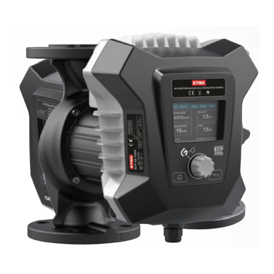
- Page 1 Use in HVAC Systems Suitable Electronic,Intelligent Circulators User Manual ECP-F Series...
-
Page 2: Table Of Contents
1. Instructions for use 2. Cautions 3. Product Overview 4. Product Installation 4.1 Installation location 4.2 Installation 4.3 Installation direction 4.4 Control box position 4.5 Electronical installation 5. Wiring Diagram 5.1 Power cord wiring method 5.2 Signal line wiring method 5.3 Connect external control 5.3.1 External communication is RS485 and the protocol is Modbus RTU... -
Page 3: Instructions For Use
1. Instructions for use Dear users, thank you for choosing the ECP-F series circulation pump. Please check carefully whether the received product is compatible with the ordered product, whether the accessories and user manuals are complete, and whether there is any damage during transport. -
Page 4: Cautions
2. Cautions In order to ensure personal safety, please read the following information carefully before you install, operate, repair or maintain. Warning The power supply used must be consistent with the power supply identified on the product. The user must confirm that only qualified personnel with professional certification and proficiency in this manual can install and maintain this product. - Page 5 Attention This product should be placed out of the reach of children. After installation, take isolation measures to avoid children's proximity Attention This product should be stored in a dry, well-ventilated place with low temperature. www.etna.com.tr...
-
Page 6: Product Overview
3. Product Overview ECP-F series variable frequency shielded circulation pump (hereinafter referred to as electronic pump), the electronic pump is mainly composed of four parts: motor, pump, seal and controller. The motor is a shielded motor with a permanent magnet rotor, and the drive is controlled by a special inverter. - Page 7 Outline structure diagram Pump Body Housing Cover Display Knob Barrel Button Wiring Post Internal structure diagram Outlet Inlet www.etna.com.tr...
-
Page 8: Product Installation
4. Product Installation 4.1 Installation location The pump should be installed indoors. 4.2 Installation When installing a circulation pump, the arrow on the pump casing indicates the direction of flow of the liquid through the pump.When installed, the shaft of the electronic pump must be horizontal. -
Page 9: Control Box Position
Unscrew and remove the four socket head cap screws securing the pump body; c. Rotate the motor to the desired position and align the four screw holes; d. Reinstall the screws and tighten them diagonally clockwise; e. Open the inlet and outlet valves. www.etna.com.tr... -
Page 10: Electronical Installation
4.5 Electronical installation Attention Perform electronical connection and protection according to local regulations. Check that the supply voltage and frequency values match those listed on the nameplate. Warning - Electronic shock - Death or serious injury - Connect the pump to an external electronical switch with a minimum contact gap of 3 mm between the electrodes. -
Page 11: Wiring Diagram
Rotate the knob slowly, after the knob hole on the mask is aligned with the control rod, fasten the cover with the housing screw 5. Wiring Diagram Example diagram of a plug-connected motor with mains switch, backup fuse and additional protective equipment www.etna.com.tr... -
Page 12: Power Cord Wiring Method
5.1 Power cord wiring method N line L line Ground Serial Describe number Connect the pull-out terminal of the power supply line: 1x220 - 240V, 50/60Hz Pull-out terminals for connecting the control board (10 pcs.) The brown wire of the power cord is connected to the L mark (live wire) on the control panel, the blue wire is connected to the N mark (neutral wire), and the yel- low-green wire is connected to the PE mark (ground). -
Page 13: Signal Line Wiring Method
RS485 positive terminal 5.3 Connect external control 5.3.1 External communication is RS485 and the protocol is Modbus RTU The communication line of the water pump needs to correspond to the A and B signals of the external controller. New sletter www.etna.com.tr... -
Page 14: Product Introduction
ALP Pompa Teknolojileri A.Ş. Dudullu Organize Sanayi Bölgesi 2. Cad. No: 14 34775 Ümraniye - İstanbul / Türkiye Tel : +90 216 561 47 74 (Pbx) • Fax : +90 216 561 47 50 www.etna.com.tr • info@etna.com.tr ECP 50-120F S/N. I[A]... -
Page 15: Insulation Foam
The water pump foam for the heating system is attached with the pump. Before installing the water pump, remove the heat insulating foam, and then put the foam on the pump body after the installation is completed. www.etna.com.tr... -
Page 16: Pump Control Modes
6.4 Pump Control Modes (Take ECP-F 50-120 as an example) Proportional pressure curve(PP1,PP2 or PP3) Proportional pressure control is used to adjust the pump performance according to the actual system heat demand, but the pump performance depends on the required pump curve PP1, PP2 or PP3. - Page 17 Pump speed adjustment range 1200-4200 rpm, 60 rpm, user adjustable. Figure 3: Constant speed curve/setting Choosing the correct constant speed setting depends on the characteristics of the heating system. www.etna.com.tr...
-
Page 18: Initial Startup And Operation
7. Initial startup and operation 7.1 Before start Warning Before starting the electronic pump, make sure the system is full of liquid, air has been completely removed, and the inlet of the electronic pump must reach the minimum inlet pressure. 7.2 Evacuate the pump The electronic pump is vented through the system, which must be vented at the highest point. -
Page 19: Product Setup
Warning and Alarms Sabit hız talimatı pressure Yardımcı arıza Current Failure önerisi Fault Log Medium F0,F6,F8,F12,F14 Fault Code High F1,F2,F3,F7,F13 Constant pressure F9,F10,F11 Constant pressure setting Constant speed Constant speed Versiyon setting Language set 中中 English Default set LCD off time www.etna.com.tr... -
Page 20: Home
7.4.3 "Home" Index "Home" Press Open the "Home" menu This menu provides the following functions • "Control Mode" • "Set point" • "Estimated Flow" • "Head" "Low flow indication" The pump may experience low flow due to, for example, closed valves.In the case of flow below 3m3/h, it will be displayed in the "Home"... -
Page 21: Status
• "Warnings and Alarms" 7.4.5 "Settings" Index "Home">"Status" Press and turn the knob clockwise to enter the "Status" This menu provides the following functions • "Running mode" • "Control Mode" • "Language set" • "Default set" • "LCD off time" www.etna.com.tr... - Page 22 Operation mode Index "Home">"Settings">"Operation mode" This menu provides the following functions • "Normal" • "Stop" • "Min speed" • "Max speed" Control mode Auto adapt Flow adapt Constant pressure Constant speed İndex "Home">"Status">"Control mode" press and turn the knob clockwise to enter the "Status"...
- Page 23 This menu allows you to return to the default factory setting, which sets the proportional pressure of the control mode to "Medium". LCD off time "Home">"Assist">LCD off time This menu allows you to return to the default factory setting, which sets the LCD off time to 60s www.etna.com.tr...
-
Page 24: Assist
7.4.6 "Assist" Index "Home">"Assist" This menu provides the following functions "Date,time set" "Control mode instruction" "Assisted fault advice" "Version" Date,time set "Home">"Assist">Date,time set This menu enables date and time setting. Control mode instruction "Home">"Assist">Control mode instruction This menu describes the characteristics of the control mode Assisted fault advice "Home">"Help">Assisted fault advice This menu gives instructions and corrective actions for pump failures. -
Page 25: Troubleshooting Table
Attention Pressurization system Mild or moderate personal injury Before disassembling the pump, drain the system or close the isolation valves at both ends of the pump. The pumped liquid can be hot and under high pressure. www.etna.com.tr... -
Page 26: Fault Cause And Finding
8.2 Fault Cause and Finding Auto reset & Alarm Exclusion method Fault Codes restart Contact the after-sales EEPROM failure department The alarm is automatically cleared Busbar over voltage within 30s, confirm whether the fault fault still exists. The alarm is automatically cleared Busbar under within 30s, confirm whether the voltage fault... -
Page 27: Technical Data
Attention The minimum relative inlet pressure applies to pumps installed at sea level up to 300 m. For altitudes above 300 m, the required relative inlet pressure must be increased by 0.01 bar for every 100 m of altitude. www.etna.com.tr... -
Page 28: Dimension
10. Dimensions Dimensions Pump type ECP32-120F 266 220 110 226 113 212 379 312 242 100 140 ECP40-80F 266 220 110 226 113 212 382 312 242 110 150 ECP40-100F 266 220 110 226 113 212 382 312 242 110 150 ECP40-120F 281 220 125 226 113 212 382 312 242 110 150... -
Page 29: Maintenance
12. Warranty Terms The warranty period of ECP-F series circulation pump is 2 (two) years from the date of purchase. During the warranty period, free repair and maintenance service will be provided for malfunctions caused by manufacturing defects. - Page 30 Dudullu Organize Sanayi Bölgesi 2. Cad. No: 14 34775 Ümraniye - İstanbul / Türkiye Tel : +90 216 561 47 74 (Pbx) • Fax : +90 216 561 47 50 www.etna.com.tr • info@etna.com.tr...
Need help?
Do you have a question about the ECP-F Series and is the answer not in the manual?
Questions and answers