Summarization of Contents
Specifications
Model Information
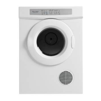
Details specific Fisher & Paykel compact dryer models and their features.
Dimensions
Provides physical dimensions (height, width, depth) for DE40F56 and DE50F56 models.
Packed Dimensions & Weights
Specifies packed dimensions and weights for DE40F56/DE50F56 models.
Ducting & Load Capacity
Outlines ducting requirements and maximum load capacity for models.
Technical Specifications
Electrical & Power Cord Details
Details electrical specifications, power, current, and power supply cord information.
Motor Specifications
Provides specifications for Fasco and WITC motors, including power and capacitor details.
Heating Element Specifications
Outlines heating element specifications for DE40F56A, DE50F56A, and DE50F56EW models.
Thermostat & Sensors
Thermostat Operation
Details thermostat voltage, current, trip points, and reset points.
Exhaust Sensor DE50F56EW
Details the resistance values of the exhaust sensor at different temperatures.
Cabinet & Drum Specifications
Cabinet Material
States the material used for the dryer cabinet.
Drum Specifications
Lists material, volume, speed, dimension, and airflow rate for various dryer drums.
Principles of Operation
Vented Dryer Operation
Explains how a vented dryer operates, detailing air flow and heating process.
Dryer Components
Mechanical System Overview
Describes the drum drive system, including motor, belt, drum mounting, and heater plate.
Temperature Control Components
Explains the function and operating points of thermostats and the exhaust sensor.
Heating Element
Details the heating element, its wattage, circuits, and how it's energized.
Door Lock & Switch
Door Lock Mechanism
Describes the mechanical locking mechanism of the dryer door.
Door Micro Switch Function
Explains the function and connection of the door micro switch for different models.
Electronic Control & Motor
Electronic Module DE50F56EW
Describes the functions of the electronic module in controlling the dryer.
Main Motor Details
Details the type of motor, its speed, capacitor, and control method for different models.
Component Testing Procedures
Motor Testing
Details methods to test motor resistance at the control panel and directly at the motor.
NTC Testing
Describes how to measure the NTC resistance at the PCB connector for DE50F56EW.
Disassembly Procedures
Timer Knob & Control Panel Removal
Instructions for removing timer knobs and control panels on specific models.
Top Panel Removal
Detailed steps for removing the top panel of the dryer.
Disassembly Procedures (Continued)
Rear Panel Removal
Steps for removing the rear panel of the dryer.
Drum Removal
Detailed steps for removing the drum assembly from the dryer.
Drum Bearing Replacement
Instructions for replacing front and rear drum bearings on various models.
Air Duct & Felt Seal Removal
Procedures for removing bearing holder, air duct, and felt seal.
Disassembly Procedures (Further Steps)
Fan Removal
Steps for removing the fan assembly for DE40F56 and DE50F56 models.
Motor Removal
Detailed steps for removing the motor from the dryer assembly.
Pulley & Jockey Pulley Removal
Procedures for removing motor driving pulleys and jockey pulleys.
Disassembly Procedures (Final Steps)
Timer Removal
Instructions for removing the timer assembly from the dryer.
Electronic Controller Removal
Steps for safely removing the electronic controller module.
Door Assembly Removal
Detailed steps for removing the dryer door assembly.
Door Switch Removal
Instructions for removing the door switch from various models.
Tools & Equipment
Required Measuring Instruments
Lists necessary meters like Ampere Meter, Watt meter, and Multi Meter.
Required Tools
Lists essential tools such as screwdrivers, sockets, Allen keys, and pliers.
Safety Equipment
Specifies the use of an anti-static wrist strap for safe handling.
Electronic Module Connection Check
LED & Button Test
Procedure to test LEDs and buttons on the control panel for functionality.
Drum Rotation & Element Check
Tests drum rotation and heating element operation using amp/watt meters.
Exhaust Sensor & Door Switch Test
Test Procedure
Steps to test the exhaust sensor and door switch functionality.
Fault Indication
Describes how faults are indicated during the sensor and switch test.
Fault Modes
Fault Code Overview
Explains how fault codes are displayed and how to initially troubleshoot.
Faulty Exhaust Sensor (Code 0101)
Details the action required for a faulty exhaust sensor diagnosis.
Fault Modes (Continued)
Exhaust Sensor Shorted to Cabinet (Code 1010)
Action for diagnosing an exhaust sensor shorted to the dryer cabinet.
Faulty Exhaust or Ambient Sensor (Code 0110)
Diagnosis and action for faulty exhaust or ambient sensors.
Over Temperature (Code 1101)
Checks for airflow restrictions causing over-temperature faults.
Fault Modes (Additional)
Brown Out (Code 1111)
Action for diagnosing brown outs related to low supply voltage.
Other Fault Codes
Refers to PCB assembly faults requiring module replacement.
Testing the Exhaust Sensor
Sensor Resistance Measurement
Details how to measure the thermistor resistance at room temperature.
Door Switch Adjustment
Adjustment Procedure
Specifies how to adjust the door switch for proper pause activation.
Brown Out
Low Voltage Condition
Describes brown outs caused by low mains voltage and how to restart.
Wiring Diagrams
Electronic Dryer DE50F56E Wiring
Diagram showing wiring connections for the electronic dryer model.
Resistance Table
Provides resistance values for key components like element, capacitor, and motor.
Wiring Diagrams (Analogue Models)
Analogue Dryer DE40F56AW Wiring
Diagram showing wiring connections for the DE40F56AW analogue dryer.
Analogue Dryer DE40F56A Wiring
Diagram showing wiring connections for the DE40F56A analogue dryer.
Analogue Dryer DE50F56AW Wiring
Diagram showing wiring connections for the DE50F56AW analogue dryer.
Analogue Dryer DE50F56A Wiring
Diagram showing wiring connections for the DE50F56A analogue dryer.
Dryer Sequence Chart
DE40F56AW & DE50F56AW Sequence
Details the timing and operation sequence for analogue models.
Dryer Sequence Chart (Push to Start)
DE40F56A2 & DE50F56A2 Sequence
Details the timing and operation sequence for push-to-start models.
Common Drying Problems
Creasing & Lint Transfer
Troubleshooting advice for creasing and lint transfer issues.
Tangling & Uneven Drying
Solutions for tangling and uneven drying performance.
Stiff Fabrics & Shrinkage
Advice on preventing stiff fabrics and shrinkage during drying.


Need help?
Do you have a question about the DE40F56A2 and is the answer not in the manual?
Questions and answers