Advertisement
Quick Links
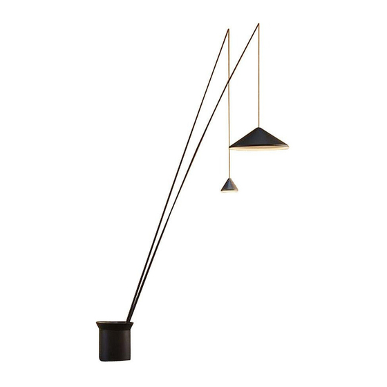
ASSEMBLY INSTRUCTIONS
SUPPLIED MATERIAL
1.
Allen key / Llave allen / Imbußschlüssel
1
Key / Llave / Schlüssel
2
Rod / Caña / Stange
3
Shade / Pantalla / Schirm
4
Base / Base / Fuß
5
6
Counterweight / Contrapeso / Gegengewicht
TECHNICAL SPECIFICATIONS
North
Design by Arik Levy
INSTRUCCIONES DE MONTAJE
MATERIAL SUMINISTRADO
2.
ESPECIFICACIONES TÉCNICAS
3.
5600
5605
2 un.
2 un.
1 un.
1 un.
2 un.
2 un.
2 un.
2 un.
1 un.
1 un.
4 un.
4 un.
MONTAGEANLEITUNG
GELIEFERTES MATERIAL
4.
5.
TECHNISCHE DATEN
6.
Advertisement

Related Manuals for VIBIA 5600


Summarization of Contents
Safety and Installation Precautions
Electrical Safety
Ensure the mains power is switched off before installation to prevent electrical hazards.
Surface Mounting Considerations
Select appropriate fixings based on the installation surface for secure lamp mounting.
Surface Integrity Check
Verify the installation surface will not be damaged during the process.
Damaged Cable Replacement
Damaged cables must be replaced by authorized personnel to avoid risks.
Indoor Usage Limitation
The lamp is intended for indoor use only, excluding humid environments like bathrooms.
Manual Reading Recommendation
Read the manual before installation and keep instructions for future reference.
Two-Person Installation
Installation and uninstallation require the assistance of at least two people.
Disassembling the Lamp Housing
Removing the Cover and Screws
Remove the cover by unscrewing and detaching it from the main body.
Detaching the Carcass
Loosen and pull the carcass upwards to fully disassemble it.
Base and Electrical Connection
Connecting the Base Plug
Prepare the base for electrical connection using the attached Schuko plug.
Removing Levelling Feet
Remove levelling feet if using existing electrical connection cable.
Connecting Existing Installation Cable
Route existing installation cable through the base and connect it in the white connector box.
Securing to Floor and Counterweights
Floor Attachment
Secure the lamp base to the floor using appropriate screws and plugs.
Removing Foundation Fasteners
Undo nuts and washers from the foundation bolts.
Installing Counterweights
Place and affix counterweights using nuts and washers, ensuring they don't protrude.
Positioning Carcass and Cable Management
Positioning the Carcass
Position the carcass by pressing down and rotating it into the fastening holes.
Securing Carcass Screws
Tighten the three gold-coloured screws through the slots with a screwdriver.
Unrolling the Power Cable
Unroll the power cable for further connections.
Rod Extension and Identification
Extending and Securing Rods
Extend and rotate rods to tighten them securely, guiding the electrical cable.
Rod Identification and Slotting
Identify rods by number and insert them into the corresponding available slot.
Adjusting Rod and Cable Heights
Adjusting Rod Height and Angle
Insert rod into slot, adjust height/angle, and tighten with a screwdriver.
Adjusting Cable Height for Shades
Adjust cable height by pulling from either end to raise or lower the shades.
Cable Insertion and Second Rod Assembly
Inserting Cable into Rod Holder
Insert the electrical cable into the groove of the rod holder.
Assembling Second Rod and Initial Height Adjustment
Assemble the second rod and adjust cable height without attaching shades.
Affixing the Shades
Attaching Shades to Rods
Affix the shades to the corresponding rods, noting dimensions and rod lengths.
Connecting Terminals and Securing Shade Element
Connecting Shade Terminals
Connect the supplied cable terminals to the shade terminals securely.
Securing Shade Element (M)
Screw element (M) by hand, using the supplied key if needed, until flush with shade top.
Final Height Adjustment and Switch Connection
Adjusting Final Shade Heights
Adjust shade heights with assistance, one holding the shade, the other pulling the cable.
Connecting Central Core Switches
Connect the switches (R) to the central core connectors.
Cable Storage and Cover Connection
Storing Excess Cable
Roll up the excess cable and store it neatly within the base.
Connecting the Cover Connector
Plug in the connector (P) from the cover, identified with a sticker.
Final Assembly: Cover, Screws, and Stones
Positioning and Securing the Cover
Position the cover (B) at an angle and align rods with openings, avoiding scratches.
Installing Cover Screws
Insert and tighten the three screws (A) to secure the cover.
Placing Decorative Stones
Place the provided stones over the cover, ensuring the central button is accessible.
Adjusting Rod Positions (Alternative)
Alternative Rod Positioning Instructions
Follow specific steps to change the position of rod 89, noting angle differences.
Managing Rod Positioning Guides
Remove and reposition the guide (S) to accommodate the alternative rod position.
Cover Protectors and Final Adjustments
Managing Cover Protective Covers
Adjust protective plastic covers (T) on the cover for rod passage and unused gaps.
Need help?
Do you have a question about the 5600 and is the answer not in the manual?
Questions and answers