
Related Manuals for Avid CNC NEMA 34


Summarization of Contents
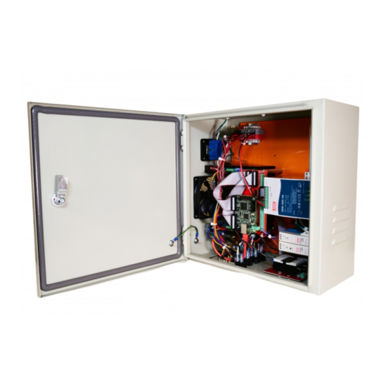
System Overview
Major Components
Identifies key external components of the CNC controller enclosure.
System Requirements
Size Requirements
Provides dimensional drawings and specifications for the control box.
Initial Setup Procedures
Plug and Play Spindle Connections
Guides connection for Plug and Play Spindle/VFD systems.
PRO CNC Plasma System Connections
Guides connection for PRO CNC Plasma systems.
Relay 1 Output Connections
Explains the function and control of Relay 1 output.
3rd Party Torch Connections
14-Pin Control Cable Pinout
Details the pin assignments for the 14-pin control cable.
System Settings
Power Settings
Shows how to locate the voltage selection switch on power supplies.
NEMA 23 5th Drive Upgrade
Disconnect Components
First step in upgrading to a 5th drive: disconnecting components.
Drive Installation
Instructions for installing a motor drive onto the chassis plate.
Capacitor Installation
How to attach the capacitor to the power supply.
Power Supply Installation
Connecting drive power and capacitor wires to the power supply.
Wiring Installation
Details the wiring process for the new motor drive and power supply.
Reconnect Components
Reinstalling all components in reverse order after upgrade.
NEMA 34 5th Drive Upgrade
Disconnect Components
Disconnecting components for NEMA 34 5th drive upgrade.
Drive Installation
Installing a motor drive for NEMA 34 systems.
Wiring Installation
Installing wiring for the new motor drive in NEMA 34 systems.
Capacitor Installation
Attaching the capacitor to the power supply for NEMA 34 upgrade.
Reconnect Components
Reinstalling components after NEMA 34 5th drive upgrade.
Adding Additional IO
Using ESS and Breakout Boards
Details connecting external breakout boards to the ESS for expanded IO.
Schematics
CRP850-00E Break-out-Board
Diagram of the CRP850-00E breakout board connections.
Common Connector Pinouts
M12 Sensor Inputs
Pinout details for M12 sensor input connectors.
14-pin Control Cable
Female Connector Pinout
Pinout diagram for the female 14-pin control cable connector.
Male Connector Pinout
Pinout diagram for the male 14-pin control cable connector.
Wiring Diagrams
NEMA 23 Systems
Wiring diagram for NEMA 23 4-axis (5 motor drivers) systems.
Need help?
Do you have a question about the NEMA 34 and is the answer not in the manual?
Questions and answers