Table of Contents
Advertisement
Quick Links
Advertisement
Table of Contents

Related Manuals for Avid CNC Plug and Play


Summary of Contents for Avid CNC Plug and Play
- Page 1 Plug and Play CNC Controller Technical Manual v2022Q1.2, 17.4 Model Revision...
-
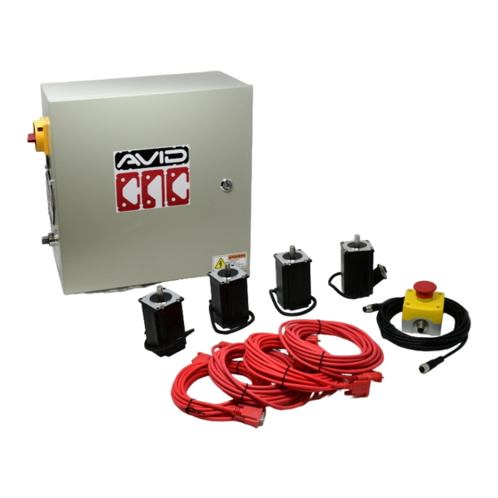
Page 2: System Overview
System Overview Major Components CNC Controller Version 2022Q1.2 Technical Manual © 2022 Avid CNC 17.4 Model Revision All Rights Reserved... - Page 3 CNC Controller Version 2022Q1.2 Technical Manual © 2022 Avid CNC 17.4 Model Revision All Rights Reserved...
-
Page 4: Emergency Stop
The emergency stop system is a normally closed circuit and must be plugged in for the CNC controller to operate. It is recommended to keep it within easy reach during machine operation so it is quickly accessible if the machine needs to be emergency stopped. CNC Controller Version 2022Q1.2 Technical Manual © 2022 Avid CNC 17.4 Model Revision All Rights Reserved... - Page 5 To activate the emergency stop, press down on the red button. The machine will come to an immediate stop and all outputs connected to the CNC controller will be turned off. CNC Controller Version 2022Q1.2 Technical Manual © 2022 Avid CNC 17.4 Model Revision All Rights Reserved...
- Page 6 In order to clear the emergency stop, twist the red button clockwise until it releases. CNC Controller Version 2022Q1.2 Technical Manual © 2022 Avid CNC 17.4 Model Revision All Rights Reserved...
- Page 7 This works as a safety measure and allows you to perform maintenance, manually move the machine, or disconnect and reconnect motors without any danger to the motors or drives. CNC Controller Version 2022Q1.2 Technical Manual © 2022 Avid CNC 17.4 Model Revision All Rights Reserved...
-
Page 8: System Requirements
18in (450mm) 8in (205mm) 19in (480mm) AVID CNC P/N: CRP800-00E PART REV: DWG REV: 00001 SCALE: SHEET 1 OF 1 DO NOT SCALE DRAWING CNC Controller Version 2022Q1.2 Technical Manual © 2022 Avid CNC 17.4 Model Revision All Rights Reserved... -
Page 9: Power Requirements
Plug & Play Controller should be powered with 200+ VAC. Plug and Play Spindle / VFD Systems: Please see the Power Requirements section in our Plug and Play Spindle / VFD Manual. CNC Controller Version 2022Q1.2 Technical Manual ©... -
Page 10: Initial Setup
Router toggle button in Mach4 or by G-code with M03 (spindle ON) and M05 (spindle OFF) commands. Control a dust collector, coolant system, or general AC load: When Avid CNC's version of Mach4 is con gured with a spindle or plasma cutting tool, relay 1 can be controlled either manually or using G-code. To manually operate the relay,... - Page 11 Spindle or plasma cutting tool: Use M07 to turn relay 2 on and M09 to turn BOTH relay 1 and relay 2 off. † The C13 type relay power plugs/sockets are rated for 15A in North America and 10A in most international regions. CNC Controller Version 2022Q1.2 Technical Manual © 2022 Avid CNC 17.4 Model Revision All Rights Reserved...
- Page 12 The ratio must be 50:1 (used by Hypertherm and preset in the Avid CNC Mach4 pro le), 40:1, 30:1, 20:1, 16.67:1, or 15:1. Note: Do not connect raw tip voltage, this will damage the TMC3in1.
- Page 13 Not all pins are populated for connectors on the CRP860-00E IO breakout board. Sensor and Aux inputs: Pin 2 (Normally Closed) is not populated E Stop input: Pin 4 (Normally Open) is not populated CNC Controller Version 2022Q1.2 Technical Manual © 2022 Avid CNC 17.4 Model Revision All Rights Reserved...
-
Page 14: Power Settings
For NEMA 34 systems, the switch to change input voltages can be found on the power supply towards the top of the CNC controller enclosure. CNC Controller Version 2022Q1.2 Technical Manual © 2022 Avid CNC 17.4 Model Revision All Rights Reserved... - Page 15 The second power supply in a NEMA 23 5-axis system will be smaller than those shown above. The switch to change input voltages on that power supply will be located on the top of the power supply. CNC Controller Version 2022Q1.2 Technical Manual © 2022 Avid CNC 17.4 Model Revision All Rights Reserved...
-
Page 16: Dip Switch Settings
CRP5056 for 4.2A 3/8" Nema 23 motors If you are using an Avid CNC rotary axis on a NEMA 23 system, be sure the rotary axis motor is hooked up to the 5th drive with that drive's DIP switch positions are set as shown below. - Page 17 The jumper pins shown here can provide 5V to pin 26 of their adjacent header, port 1 or port 2. The ESS comes pre- con gured in the CNC controller with these jumpers connected on port 1 and port 2. CNC Controller Version 2022Q1.2 Technical Manual © 2022 Avid CNC 17.4 Model Revision All Rights Reserved...
- Page 18 Warning Ensure your plug and play control box is powered off with the power cable disconnected from the box. It is also recommended to remove the control box from the machine for easier installation of the motor drive. CNC Controller Version 2022Q1.2...
- Page 19 The st step in upgrading your NEMA 23 system with a 5th drive will be to remove the gland plate and disconnect the breakout board. Unplug the four motor drivers and the ethernet cable connected to the breakout board. CNC Controller Version 2022Q1.2 Technical Manual © 2022 Avid CNC 17.4 Model Revision All Rights Reserved...
- Page 20 Remove the gland plate fasteners, disconnect the ribbon cable attached to the relay board, and pull the gland plate away from the box. CNC Controller Version 2022Q1.2 Technical Manual © 2022 Avid CNC 17.4 Model Revision All Rights Reserved...
- Page 21 Remove the two fasteners holding the breakout board in place and carefully remove the board from the drives. Move the board into the opening left by the gland plate. CNC Controller Version 2022Q1.2 Technical Manual © 2022 Avid CNC 17.4 Model Revision All Rights Reserved...
-
Page 22: Drive Installation
Dip switches in ON position: 1, 3, 6, 7 Dip switches in OFF position: 2, 4, 5, 8 CNC Controller Version 2022Q1.2 Technical Manual © 2022 Avid CNC 17.4 Model Revision All Rights Reserved... - Page 23 Partially install one of the M4 screws into a pre-drilled hole on the chassis plate, leaving room for the motor drive to slide under. CNC Controller Version 2022Q1.2 Technical Manual © 2022 Avid CNC 17.4 Model Revision All Rights Reserved...
- Page 24 Slide the drive into place and fasten with the second M4 screw. Tighten both fasteners. CNC Controller Version 2022Q1.2 Technical Manual © 2022 Avid CNC 17.4 Model Revision All Rights Reserved...
- Page 25 Plug the breakout board back into the drives and fasten with the two mounting screws. CNC Controller Version 2022Q1.2 Technical Manual © 2022 Avid CNC 17.4 Model Revision All Rights Reserved...
-
Page 26: Capacitor Installation
3. Capacitor Installation Attach the capacitor to your existing power supply using the provided (2) M3 x 6mm socket head cap screws. CNC Controller Version 2022Q1.2 Technical Manual © 2022 Avid CNC 17.4 Model Revision All Rights Reserved... -
Page 27: Power Supply Installation
Wire Color Power Supply Terminal Capacitor Capacitor Black Motor Drive Motor Drive Black Terminal Blocks Black Terminal Blocks White ⏚ (ground) Terminal Blocks Green CNC Controller Version 2022Q1.2 Technical Manual © 2022 Avid CNC 17.4 Model Revision All Rights Reserved... - Page 28 Ensure that the switch on top of the power supply is set to the correct voltage for your control box. This will be 115V unless you speci cally ordered your control system setup for 230V. CNC Controller Version 2022Q1.2 Technical Manual © 2022 Avid CNC 17.4 Model Revision All Rights Reserved...
- Page 29 Install the power supply onto the chassis plate using the provided (2) T20 M6 x 8mm screws. CNC Controller Version 2022Q1.2 Technical Manual © 2022 Avid CNC 17.4 Model Revision All Rights Reserved...
-
Page 30: Wiring Installation
You will now install the wiring for the new motor drive and power supply. Press out the rubber hole plug from the A axis port on the gland plate. Fasten the DB9 bulkhead connector to the gland plate with the provided threaded studs. CNC Controller Version 2022Q1.2 Technical Manual © 2022 Avid CNC 17.4 Model Revision All Rights Reserved... - Page 31 Attach the blue, yellow, green, and red wires from the DB9 connector to the motor drive's phoenix connector. Also attach the red and black power wires from the power supply to this connector. Connect the wires in the correct order, as shown below. CNC Controller Version 2022Q1.2 Technical Manual © 2022 Avid CNC 17.4 Model Revision All Rights Reserved...
- Page 32 Remove the nut on the grounding wire stud, located at the bottom left corner of the box. Stack the DB9 connector's ground wire on top of the main grounding wires and fasten by reinstalling the nut. CNC Controller Version 2022Q1.2 Technical Manual © 2022 Avid CNC 17.4 Model Revision All Rights Reserved...
- Page 33 Install the wires into the terminal blocks: Green wire to green terminal block Black wire to red terminal block White wire to white terminal block CNC Controller Version 2022Q1.2 Technical Manual © 2022 Avid CNC 17.4 Model Revision All Rights Reserved...
- Page 34 6. Reconnect Components Reinstall all components, in the reverse order in which they were removed. Ensure all components that were unplugged are plugged back in securely. CNC Controller Version 2022Q1.2 Technical Manual © 2022 Avid CNC 17.4 Model Revision All Rights Reserved...
- Page 35 Warning Ensure your plug and play control box is powered off with the power cable disconnected from the box. It is also recommended to remove the control box from the machine for easier installation of the motor drive. CNC Controller Version 2022Q1.2...
- Page 36 The st step in upgrading your NEMA 34 system with a 5th drive will be to remove the gland plate and disconnect the breakout board. Unplug the four motor drivers and the ethernet cable connected to the breakout board. CNC Controller Version 2022Q1.2 Technical Manual © 2022 Avid CNC 17.4 Model Revision All Rights Reserved...
- Page 37 Remove the gland plate fasteners, disconnect the ribbon cable attached to the relay board, and pull the gland plate away from the box. CNC Controller Version 2022Q1.2 Technical Manual © 2022 Avid CNC 17.4 Model Revision All Rights Reserved...
- Page 38 Remove the two fasteners holding the breakout board in place and carefully remove the board from the drives. Leave the breakout board in the box and do not disconnect any extra wires. CNC Controller Version 2022Q1.2 Technical Manual © 2022 Avid CNC 17.4 Model Revision All Rights Reserved...
- Page 39 Dip switches in ON position: 1, 2, 3, 6, 7 Dip switches in OFF position: 4, 5, 8 CNC Controller Version 2022Q1.2 Technical Manual © 2022 Avid CNC 17.4 Model Revision All Rights Reserved...
- Page 40 Partially install one of the M4 screws into a pre-drilled hole on the chassis plate, leaving room for the motor drive to slide under. CNC Controller Version 2022Q1.2 Technical Manual © 2022 Avid CNC 17.4 Model Revision All Rights Reserved...
- Page 41 Slide the drive into place and fasten with the second M4 screw. Tighten both fasteners. CNC Controller Version 2022Q1.2 Technical Manual © 2022 Avid CNC 17.4 Model Revision All Rights Reserved...
- Page 42 Plug the breakout board back into the drives and fasten with the two mounting screws. CNC Controller Version 2022Q1.2 Technical Manual © 2022 Avid CNC 17.4 Model Revision All Rights Reserved...
- Page 43 You will now install the wiring for the new motor drive. Remove the clear cover on the power supply's terminals and install the red and black wires from the provided harness. Fully tighten the terminal screws and replace the cover. CNC Controller Version 2022Q1.2 Technical Manual © 2022 Avid CNC 17.4 Model Revision All Rights Reserved...
- Page 44 Press out the rubber hole plug from the A axis port on the gland plate and attach the XLR bulkhead connector. Fasten the connector with the provided screws and nuts, in the diagonal pattern used on the other XLR connectors. CNC Controller Version 2022Q1.2 Technical Manual © 2022 Avid CNC 17.4 Model Revision All Rights Reserved...
- Page 45 Also attach the red and black wires from the power supply to this connector, using the terminals on the right (as shown below). CNC Controller Version 2022Q1.2 Technical Manual © 2022 Avid CNC 17.4 Model Revision All Rights Reserved...
- Page 46 Remove the nut on the grounding wire stud, located at the bottom left corner of the box. Stack the XLR connector's ground wire on top of the main grounding wires and fasten by reinstalling the nut. CNC Controller Version 2022Q1.2 Technical Manual © 2022 Avid CNC 17.4 Model Revision All Rights Reserved...
- Page 47 4. Capacitor Installation Attach the capacitor to the left power supply using the provided (2) M3 x 6mm socket head cap screws. CNC Controller Version 2022Q1.2 Technical Manual © 2022 Avid CNC 17.4 Model Revision All Rights Reserved...
- Page 48 Connect the capacitor harness to the power supply on the right as shown below. Connect the black wire to V- and the wire to CNC Controller Version 2022Q1.2 Technical Manual © 2022 Avid CNC 17.4 Model Revision All Rights Reserved...
- Page 49 Reinstall all components, in the reverse order in which they were removed. Ensure all components that were unplugged are plugged back in securely. Your plug and play control system is now upgraded and ready to operate a 5th motor. If you experience any trouble with this set up, please feel free to Contact Us.
- Page 50 A ribbon cable with appropriate connectors. To power the breakout board from the ESS a 26-pin connector on both ends is required. A breakout board with appropriate connectors and opto-isolation for the input signals. For complete information see Warp9's documentation: warp9td.com/index.php/documentation/doc-ess CNC Controller Version 2022Q1.2 Technical Manual © 2022 Avid CNC 17.4 Model Revision All Rights Reserved...
- Page 51 Fault Signal Control Signal 12V IN Listed on the following pages are descriptions and port/pin assignments. Port 4 is a pass-through from Port 1 CNC Controller Version 2022Q1.2 Technical Manual © 2022 Avid CNC 17.4 Model Revision All Rights Reserved...
- Page 52 Fault Signal: This input signal terminal is speci cally designed to read a fault from an external VFD, typically from thermal overload or a disconnected spindle power cable. CNC Controller Version 2022Q1.2 Technical Manual © 2022 Avid CNC 17.4 Model Revision All Rights Reserved...
- Page 53 ENABLE +5V ENABLE Signal Spindle FWD Spindle DCM 2/14 5V GND 0-10V Out, V+ 12V GND 12V In, +12V 12V GND Fault Signal 2/13 CNC Controller Version 2022Q1.2 Technical Manual © 2022 Avid CNC 17.4 Model Revision All Rights Reserved...
- Page 54 12V GND CNC Controller Version 2022Q1.2 Technical Manual © 2022 Avid CNC 17.4 Model Revision All Rights Reserved...
- Page 55 Y+ Sensor Signal Z+ Sensor Signal AUX 2 Signal E-Stop Signal Relay 1 Control Switch Relay 2 Control Switch GND I/O 12V GND 12V GND CNC Controller Version 2022Q1.2 Technical Manual © 2022 Avid CNC 17.4 Model Revision All Rights Reserved...
- Page 56 CRP860-00E Break-out-Board FRONT VIEW Note All M12 inputs are A-coded. See M12 Sensor Inputs CNC Controller Version 2022Q1.2 Technical Manual © 2022 Avid CNC 17.4 Model Revision All Rights Reserved...
- Page 57 Phoenix Connector Terminal Blocks Terminal # Description Pin (Port 2 on CRP850-00E card) Relay 1 Control Switch 12V GND Relay 2 Control Switch 12V GND CNC Controller Version 2022Q1.2 Technical Manual © 2022 Avid CNC 17.4 Model Revision All Rights Reserved...
- Page 58 Not all pins are populated for connectors on the CRP860-00E IO breakout board. Sensor and Aux inputs: Pin 2 (Normally Closed) is not populated E Stop input: Pin 4 (Normally Open) is not populated CNC Controller Version 2022Q1.2 Technical Manual © 2022 Avid CNC 17.4 Model Revision All Rights Reserved...
- Page 59 Black Spindle (optional) Analog 10V Ref Blue/White Plasma Digital In Arc OK White/Black 3/10 Plasma Ground Blue/Black Plasma Signal GND Arc OK Ground Green/White CNC Controller Version 2022Q1.2 Technical Manual © 2022 Avid CNC 17.4 Model Revision All Rights Reserved...
- Page 60 Yellow B - Phase Blue A + Phase A - Phase Green XLR Motor Connectors Pin # Motor Phase Wire Color Green Yellow Blue CNC Controller Version 2022Q1.2 Technical Manual © 2022 Avid CNC 17.4 Model Revision All Rights Reserved...
-
Page 61: Wiring Diagrams
0-10V out 12V in Fault Vout GND SIG GND RELAY 2 IN RELAY 1 OUT CRP860-02E RELAY 1 IN RJ45 DB9 PORTS Updated 7/29/2020 CNC Controller Version 2022Q1.2 Technical Manual © 2022 Avid CNC 17.4 Model Revision All Rights Reserved... - Page 62 Vout GND SIG GND RELAY 2 IN RELAY 1 OUT RED/WHT GRN/BLK RED/BLK CRP860-02E RELAY 1 IN RJ45 WHT/BLK WHT/GRN DB9 PORTS ORG/BLK Updated 7/29/2020 CNC Controller Version 2022Q1.2 Technical Manual © 2022 Avid CNC 17.4 Model Revision All Rights Reserved...
- Page 63 0-10V out 12V in Fault Vout GND SIG GND RELAY 2 IN RELAY 1 OUT CRP860-02E RELAY 1 IN RJ45 XLR PORTS Updated 7/29/2020 CNC Controller Version 2022Q1.2 Technical Manual © 2022 Avid CNC 17.4 Model Revision All Rights Reserved...
- Page 64 Vout GND SIG GND RELAY 2 IN RELAY 1 OUT RED/WHT GRN/BLK RED/BLK CRP860-02E RELAY 1 IN RJ45 WHT/BLK WHT/GRN XLR PORTS ORG/BLK Updated 7/29/2020 CNC Controller Version 2022Q1.2 Technical Manual © 2022 Avid CNC 17.4 Model Revision All Rights Reserved...
Need help?
Do you have a question about the Plug and Play and is the answer not in the manual?
Questions and answers