Table of Contents
Advertisement
Quick Links
Advertisement
Table of Contents
Troubleshooting

Related Manuals for Faulhaber MCS 3268G024BX4 RS/CO


Summary of Contents for Faulhaber MCS 3268G024BX4 RS/CO
- Page 1 Technical Manual MCS 3242 BX4 MCS 3268 BX4 MCS 3274 BP4 WE CREATE MOTION...
- Page 2 Dr. Fritz Faulhaber GmbH & Co. KG. This document has been prepared with care. Dr. Fritz Faulhaber GmbH & Co. KG cannot accept any liability for any errors in this document or for the consequences of such errors. Equally, no liability can be accepted for direct or consequential damages resulting from improper use of the equipment.
-
Page 3: Table Of Contents
Content About this document ....................... 5 Validity of this document ..................5 Associated documents .................... 5 Using this document ....................5 List of abbreviations ....................6 Symbols and designations ..................7 Safety ..........................8 Intended use ......................8 Safety instructions ....................8 Environmental conditions .................. - Page 4 Content Maintenance and diagnostics ..................39 Maintenance instructions ..................39 Maintenance tasks ....................39 Diagnosis ....................... 40 Troubleshooting ....................40 Accessories ........................41 Warranty ......................... 42 4th edition, 26-08-2020 7000.05058, 4th edition, 26-08-20207000.05058...
-
Page 5: About This Document
Drive functions Description of the operating modes and functions of the drive Accessories manual Description of the accessories These manuals can be downloaded in pdf format from the web page www.faulhaber.com/ manuals. Using this document Read the document carefully before undertaking configuration, in particular chapter “Safety”. -
Page 6: List Of Abbreviations
About this document List of abbreviations Abbreviation Meaning Alternating Current AnIn Analogue input AGND Analogue Ground Controller Area Network CAN_L CAN-Low CAN_H CAN-High Chip Select Direct Current DigIn Digital input DigOut Digital output Electronics Filter Supply EGND Electronic Ground Electromagnetic compatibility Electrostatic discharge EtherCAT (Ethernet for Control Automation Technology) Ground... -
Page 7: Symbols And Designations
About this document Symbols and designations CAUTION! Hazards due to hot surfaces. Disregard may lead to burns. Measures for avoidance NOTICE! Risk of damage. Measures for avoidance Instructions for understanding or optimising the operational procedures Pre-requirement for a requested action 1. -
Page 8: Safety
Safety Safety Intended use The Motion Control Systems described here consist of a combination of a base motor and an integrated Motion Controller within a common housing with standard protection class IP 54. The Motion Control Systems are intended for use as slaves, and are particularly suitable for positioning tasks in the following application fields: Robotics ... -
Page 9: Environmental Conditions
Therefore the Machinery Directive does not apply to our products. The products described here are not “incomplete machines”. Therefore installation instructions are not normally issued by FAULHABER. Low Voltage Directive (2014/35/EU) The Low Voltage Directive applies for all electrical equipment with a nominal voltage of 75 to 1500 V DC and 50 to 1000 V AC. -
Page 10: Product Description
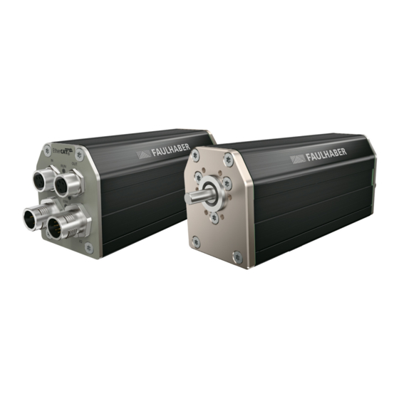
Product description General product description The FAULHABER Motion Control Systems described here are intended for controlled opera- tion of various integrated base motors. They offer different functions and operating modes, allowing complex drive tasks to be performed. Thanks to their compact design and flexible connection options, the units can be used in a wide variety of applications and require only basic wiring. -
Page 11: Product Information
Product description Product information ..Serielle Schnittstelle RS 232 Schnittstelle CANopen Schnittstelle EtherCAT BX4: Motorfamilie (BL, 4-Pol-Technologie) BP4: Motorfamilie (BL, 4-Pol-Technologie) 024: Motornennspannung 24 V Wellendurchmesser 5 mm Länge Vorbaumotor 42 mm Länge Vorbaumotor 68 mm Länge Vorbaumotor 74 mm Durchmesser Vorbaumotor 32 mm MCS: Motion Control System... -
Page 12: Product Variants
Product description Product variants The following product variants are possible: Motion Control System with axial cable outlet Motion Control System with radial cable outlet In addition to the cable outlet, the following communication interfaces can be selected: RS232 CANopen ... -
Page 13: Cable Outlet Of The Motion Control System
Product description Cable outlet of the Motion Control System 3.4.1 Axial cable outlet (standard) Fig. 2: Isometric view (left) and connector view (right) for axial cable outlet 3.4.2 Radial cable outlet (option 5451) Fig. 3: Isometric view (left) and connector view (right) for radial cable outlet 4th edition, 26-08-2020 7000.05058, 4th edition, 26-08-20207000.05058... -
Page 14: Gearhead Combination
Product description 3.4.3 Gearhead combination Fig. 4: Combination example with gearhead 32A Using option 5657 and when the base drive is directly flange-mounted or in combina- tion with attachments (e.g. gearboxes), an additional seal (O-ring), to enhance the pro- tection class of the complete system, may be installed between the drive and the attachment (see chap. -
Page 15: Connector Overview
Red (continuously flashing): The drive has switched to a fault state. The output stage will be switched off or has already been switched off. Red (error code): Booting has failed. Please contact FAULHABER Support. Green (continuous light): Connection present. Device is ready for use. -
Page 16: Installation
Installation Installation Only trained experts and instructed persons with knowledge of the following fields may install and commission the Motion Control System: Automation technology Standards and regulations (such as the EMC Directive) Low Voltage Directive Machinery Directive ... -
Page 17: Mounting On The Front Flange
Installation 4.1.2 Mounting on the front flange Fig. 6: V3 installation schematic diagram NOTICE! If the Motion Control System is installed with the shaft end facing upwards, liquids can accumulate on the upward-facing surface and damage the device. With V3 installation (see Fig. 6), make sure that no liquids can penetrate the bearings. ... - Page 18 Installation Fig. 8: Front view of the motor flange A-side with radial groove (blue) 4th edition, 26-08-2020 7000.05058, 4th edition, 26-08-20207000.05058...
-
Page 19: Mounting With Baseplate
Installation 4.1.3 Mounting with baseplate Screws and base plate are not part of the FAULHABER product portfolio and they must be provided by the user. 1. Secure the Motion Control System (1) with screws (3) to the base plate (2). -
Page 20: Electrical Connection
A short-term voltage peak during braking can damage the power supply or other con- nected devices. For applications with high load inertia, the FAULHABER Braking Chopper of the BC 5004 series can be used to limit overvoltages and thereby protect the power supply. For more detailed information see the data sheet for the Braking Chopper. - Page 21 Installation Customer application Power supply Programming adapter RS232/CAN: 6501.00283 USB: 6501.00284 RS232/CAN Fig. 10: Commissioning via programming adapter For details on pin assignment and jumper settings of the programming adapter refer to the appropriate data sheets. 4th edition, 26-08-2020 7000.05058, 4th edition, 26-08-20207000.05058...
-
Page 22: Connecting The Motion Control System
Installation 4.2.2 Connecting the Motion Control System Connections of the Motion Control System: Discrete inputs and outputs (for instance for discrete set-point specification or for con- nection of limit switches and reference switches) Communication connections Make sure that the connection cables are not longer than 3 m. To reduce the effects on the DC power supply network, ferrite sleeves (such as WE 742 700 790) can be used on the supply cables. -
Page 23: Connector Pin Assignment
Installation 4.2.3 Connector pin assignment NOTICE! Incorrect connection of the pins can damage the electronic components. Check the orientation of the pins in the diagram. EtherCAT interface connection (IN/OUT) Tab. 3: Pin assignment for the EtherCAT M8 connector, 4-pin, A-coded, viewed from the socket side Designation Meaning... - Page 24 Installation I/O connection (X2) Tab. 6: Pin assignment for the M12 connector, 12-pin, A-coded, viewed from the pin side Designation Meaning Ground connection CAN_L /RxD CAN-Low interface CAN_H /TxD CAN-High interface Power supply for external consumer loads DigOut 1 Digital output DigOut 2 Digital output DigIn 1...
-
Page 25: I/O Circuit Diagrams
Installation 4.2.4 I/O circuit diagrams AGND – AnIn Fig. 12: Analogue input circuit diagram (internal) So that the voltage drop on the supply side does not affect the speed specification value, connect the analogue input ground (AGND) to the power supply ground (GND). The analogue inputs are executed as differential inputs. -
Page 26: External Circuit Diagrams
Installation DigOut DigOut Fig. 14: Digital output circuit diagram (internal) The digital output has the following properties: Open collector switch to ground Monitored output current (switch opens in the event of an error) The digital output can be configured for the following purposes: ... - Page 27 Installation Analogue set-point specification via potentiometer with internally set offset and scaling Motion Control System AnIn 10 k AGND – Interface Fig. 16: Analogue set-point specification via potentiometer with internally set offset and scaling Connection of reference and limit switches Motion Control System 1x10 1x10...
- Page 28 Installation Connection of an external incremental encoder 2,7k DigIn1 DigIn2 Quadrature Encoder Counter DigIn3 Index Index Interface Fig. 18: Connection of an external incremental encoder Depending on the type of encoder it may be necessary to use additional pull-up resis- tors.
- Page 29 Installation Wiring with several Motion Control Systems in RS232 network operation PC or Node 1 Node n High Level Control 4,7k Fig. 20: Wiring with several Motion Control Systems in RS232 network operation Depending on the number of networked Motion Control Systems, a smaller value may be necessary for the pull-down resistor.
-
Page 30: Electromagnetic Compatibility (Emc)
Installation Electromagnetic compatibility (EMC) Follow the instructions in the following chapters to perform an EMC-compliant installa- tion. NOTICE! Drive electronics with qualified limit values in accordance with EN-61800-3: Category C2 can cause radio interference in residential areas. For these drive electronics, take additional measures to limit the spread of radio inter- ference. - Page 31 Installation AC-mains system Power adapter Filter Control Line Motor filter filter PELV Fig. 23: Interference sources in an AC-mains system Mains impedance of mains transformer – power supply connection Common-mode impedance of electronics on DC side Common-mode impedance of electronics on AC side – power supply connection Impedance of motor housing –...
-
Page 32: Functional Earthing
Installation Problem solutions The interference may vary depending on load and installation. Solution Mode of action Benefits Disadvantages Removes RF common- Does not remove all inter- 3-phase common-mode Removes common-mode mode interference ference choke / ferrite ring around interference of the MCS ... -
Page 33: Cable Routing
Installation 4.3.3 Cable routing The cable routing depends on various factors, such as: Is the cable shielded, twisted? Were interference-reducing measures taken? What material and what cable routing are used in the cable duct? Over what surface is the cable routed? Observe the following when laying the cables: ... -
Page 34: Shielding
Installation 4.3.4 Shielding Shield cables in all cases. Shield cables that are longer than 3 m with tightly meshed copper braiding. Shield all supply lines according to current guidelines/standards (e.g., IPC-A-620B) and connect using (round) shield clamp. In special cases (e.g., with pigtail) or after qualification, the shield can be omitted for the following cables: Cables with length <50 cm ... -
Page 35: Establishing The Shield Connection
Installation 4.3.4.1 Establishing the shield connection The best results when establishing a shield connection on the cable are achieved in the fol- lowing way: Fig. 27: Motor cable shield connection Outer cable shield Heat-shrink tubing Braided shield Crimp-sleeve Shield clamp 1. -
Page 36: Establishing Shield Connection With Cable Lug
Installation 4.3.4.2 Establishing shield connection with cable lug A shield connection with cable lug should be avoided whenever possible. If it is necessary, however, the connection should be established as follows. Fig. 28: Shield connection with cable lug Screw Lock washer Wall Spring washer Wire eyelet... -
Page 37: Using Filters
DC power supply 4.3.5.2 Insulation resistance The filters from FAULHABER are not intended for an insulation resistance test. Discharging of the common-mode interference with capacitors prevents a meaningful result from an insulation resistance test. -
Page 38: Error Avoidance And Troubleshooting
Installation 4.3.6 Error avoidance and troubleshooting 1. Can the problem clearly be traced back to the FAULHABER drive system? a) Switch the output stage off and on. The voltage controller mode is suitable here. b) Unplug controller supply voltages or operate controller via a separate external power supply used solely for this purpose. -
Page 39: Maintenance And Diagnostics
Maintenance and diagnostics Maintenance and diagnostics Maintenance instructions NOTICE! The housing of the Motion Control System is not resistant to solvents such as alcohols or acetone. During operation and maintenance protect the housing against contact with solvents or substances containing solvents. Maintenance tasks In principle the drives are maintenance-free. -
Page 40: Diagnosis
Red (continuously flashing): The drive has switched to a fault state. The output stage will be switched off or has already been switched off. Red (error code): Booting has failed. Please contact FAULHABER Support. Green (continuous light): Connection present. Device is ready for use. RUN LED EtherCAT Green (flashing): Device is in the Pre-Operational. -
Page 41: Accessories
Accessories Accessories Details of the following accessory parts can be found in the Accessories Manual: Connection cables Connectors Installation aids Additional equipment Programming adapter 4th edition, 26-08-2020 7000.05058, 4th edition, 26-08-20207000.05058... -
Page 42: Warranty
Warranty Warranty Products of the company Dr. Fritz Faulhaber GmbH & Co. KG are produced using the most modern production methods and are subject to strict quality inspections. All sales and deliv- eries are performed exclusively on the basis of our General Conditions of Sale and Delivery which can be viewed on the FAULHABER home page https://www.faulhaber.com/gtc and... - Page 43 DR. FRITZ FAULHABER GMBH & CO. KG Antriebssysteme Daimlerstraße 23 / 25 71101 Schönaich • Germany Tel. +49(0)7031/638-0 Fax +49(0)7031/638-100 info@faulhaber.de www.faulhaber.com 7000.05058, 4th edition, 26-08-2020 © Dr. Fritz Faulhaber GmbH & Co. KG...
Need help?
Do you have a question about the MCS 3268G024BX4 RS/CO and is the answer not in the manual?
Questions and answers