Advertisement
Quick Links
Apator S.A., 87-100 Toruń, ul. Gdańska 4a lok. C4
tel.: +48 56 61 91 244, fax: +48 56 61 91 295
www.apator.com
Zakład produkcyjny
Ostaszewo 57C, 87-148 Łysomice
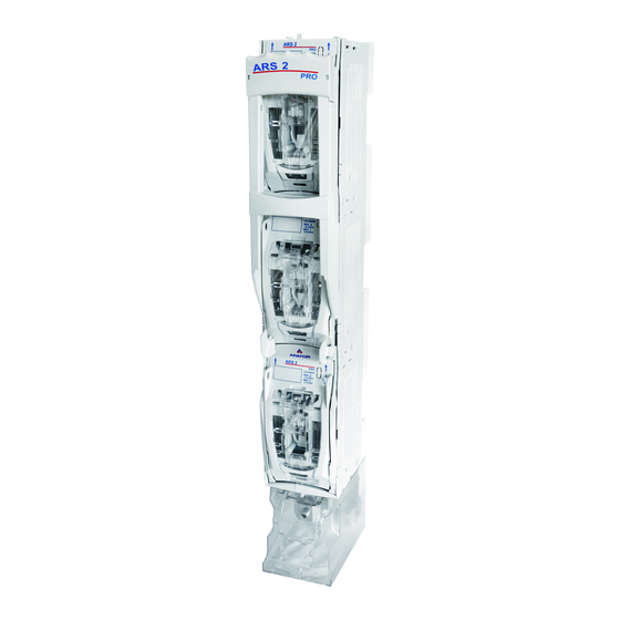
Listwowe rozłączniki izolacyjne
Vertical fuse switch disconnectors
ARS 3f;
ARS 400, ARS 2 pro, ARS 3 pro, ARS 630kVA pro, RWS 1250 pro
Instrukcja obsługi i montażu
Mounting and operation manual
ISO 9001
Manufacturing area
PN-N-18001
ISO 14001
Advertisement

Related Manuals for Apator ARS 3 pro


Summarization of Contents
Taking Off the Cover of the Disconnector
Step 1a: Handle to Release Position
Take the handle and move it to the position of release until the handle is blocked.
Step 1b: Cover Removal
Gently pull out the cover's ears in direction 'I', rotate it in direction 'II' until resistance, then remove from mechanism.
Step 1c: Handle to Operation Position
Move the handle to the 'operation/switched on' position of the disconnector.
Opening and Closing Masking Plates
Step 2a: Open Masking Plates
Open the masking plates for fixing bolts.
Step 2b: Mount Disconnector to Bus Bars
Mount disconnector to bus bars by screwing bolts in poles, then close masking plates.
Taking Off Terminal Shield and Fixing Cables
Step 3a: Remove Terminal Shield and Tighten Cables
Take off the shield for terminals and tighten output cables.
Step 3b: Mount Terminal Shield
Mount the shield for terminals.
Mounting Extra Label in Terminal Shield
Step 4a: Insert Extra Label
Insert extra label from the bottom of the shield for terminals.
Mounting Fuse Links in Cover
Step 5a: Place Fuse Link
Place fuse link or solid link in the cover catches.
Step 5b: Remove Fuse Link
Push slide element, then pull out fuse link or solid link from cover catches.
Mounting Cover with Fuse Links
Step 6a: Operation on Bus Bar Bridge
Perform operation according to point 1a) for disconnector mounted on bus bar bridge.
Step 6b: Set Cover in Guide
Set cover in guide up to resistance according to arrow 'I', rotate according to arrow 'II'.
Step 6c: Snap Cover
Snap the cover in the guide.
Step 6d: Repeat for Other Covers
Perform the above operations for subsequent covers.
Switching On the Disconnector
Step 7a: Move Handle to Closed Position
Take handle and move it firmly in direction of arrow until disconnector is completely closed.
Switching Off the Disconnector
Step 8a: Move Handle to Release Position
Take handle and move it firmly in direction of arrow until handle blocks on release.
Parking the Disconnector
Step 9a: Switch Off Disconnector
Switch off the disconnector according to point 8.
Step 9b: Press Releases
Press the releases until the handle is released.
Step 9c: Pull Handle with Releases Pressed
With releases pressed, pull the handle until resistance.
Step 9d: Move Operating Mechanism
Take operating mechanism, pull it, then move handle as shown.
Step 9e: Insert Mechanism into Cabinet
Insert operating mechanism into cabinet until resistance to get parking state.
Releasing the Parking of the Disconnector
Step 10a: Move Handle to Resistance
Take handle and move it in direction of arrow until resistance.
Step 10b: Release Handle and Pull
Press releases until handle is freed, then pull handle until resistance.
Step 10c: Insert Mechanism and Close
In this position, push mechanism into cabinet until resistance and close disconnector.
Removing Mechanism for Grounding
Step 11a: Proceed and Remove Mechanism
Proceed according to point 9 a,b,c,d, then take out operating mechanism.
Step 11b: Mount Earthing Clamp and Ground
Mount earthing clamp to bus bar using insulating pole, ground disconnector from load side with links.
Dismantling Earthing Switch and Mounting Mechanism
Step 12a: Dismantle Earthing Switch
Dismantle the earthing switch in reverse order of point 11 b.
Step 12b: Insert Mechanism and Close
Insert mechanism into cabinet until resistance, ensure correct guideline insertion, then close disconnector.
Connecting Outlet Cables from the Top
Step 13a: Remove Plates and Shield
Take out plates as per point 1 (don't lower handle) and remove terminal shield.
Step 13b: Turn Bolts Clockwise
Turn 6 bolts clockwise by 90° using a screwdriver.
Step 13c: Remove Cabinet from Base
Take the cabinet out of the base.
Step 13d: Turn Cabinet and Bolts
Turn cabinet 180°, place on base, align bolts, then turn bolts anticlockwise by 90°.
Step 13e: Finalize Top Outlet Connection
Disconnector is ready for mounting on bus bar bridge with top outlets; connect as per points 2-6.
Safety Precautions and Tool Usage
Use Insulated Tools
It is recommended to use insulated tools for safety reasons.
Need help?
Do you have a question about the ARS 3 pro and is the answer not in the manual?
Questions and answers