Advertisement
Quick Links
Apator S.A., 87-100 Toruń, ul. Gdańska 4a lok. C4
tel.: +48 56 61 91 244, fax: +48 56 61 91 295
www.apator.com
Zakład produkcyjny
Ostaszewo 57C, 87-148 Łysomice
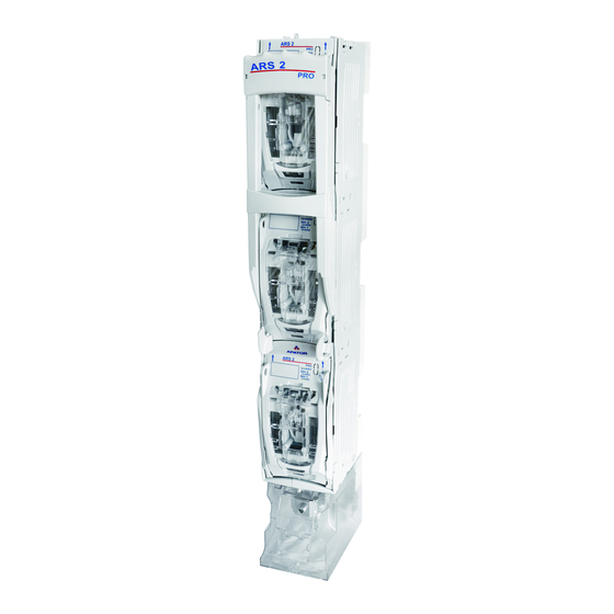
Listwowe rozłączniki izolacyjne
Vertical fuse switch disconnectors
ARS 3f;
ARS 400, ARS 2 pro, ARS 3 pro, ARS 630kVA pro, RWS 1250 pro
Instrukcja obsługi i montażu
Mounting and operation manual
ISO 9001
Manufacturing area
PN-N-18001
ISO 14001
Advertisement

Related Manuals for Apator ARS 2 pro


Summarization of Contents
Taking Off the Cover of the Disconnector
Move Handle to Release Position
Move the handle to the release position until it locks against the release mechanism.
Remove and Rotate Cover
Pull the cover ears and rotate it to remove the cover from the operating mechanism.
Move Handle to Operation Position
Move the handle to the "operation/switched on" position of the disconnector.
Fixing Disconnector to Bus Bars
Open Masking Plates
Open the masking plates for the fixing bolts.
Mount Disconnector to Bus Bars
Mount the disconnector to bus bars by screwing bolts in the poles and closing masking plates.
Remove Terminal Shield and Tighten Cables
Remove the terminal shield and tighten output cables.
Mounting Extra Label in Terminal Shield
Insert Label into Terminal Shield
Insert an extra label from the bottom of the shield for terminals.
Mounting and Dismantling Fuse Links/Solid Links
Place Fuse Link or Solid Link
Place the fuse link or solid link into the cover catches.
Remove Fuse Link or Solid Link
Push the slide element and pull out the fuse link or solid link from the cover catches.
Mounting Cover with Fuse Links/Solid Links
Perform Operation per Point 1a
Perform the operation according to point 1a) for the disconnector mounted on bus bar bridge.
Insert and Rotate Cover in Guide
Insert and rotate the cover in the guide according to the indicated directions.
Snap Cover into Guide
Snap the cover into the guide.
Repeat for Other Covers
Repeat the above operations for subsequent covers.
Switching On the Disconnector
Move Handle to Close Disconnector
Move the handle firmly to close the disconnector completely.
Switching Off the Disconnector
Move Handle to Release Position
Move the handle firmly to the release position until it locks against the release.
Parking the Disconnector
Switch Off Disconnector
Switch off the disconnector according to point 8.
Press Releases
Press the releases until the handle is released.
Pull Handle with Releases Pressed
While releases are pressed, pull the handle until resistance.
Move Operating Mechanism and Handle
Pull the operating mechanism and move the handle as shown in the figure.
Insert Operating Mechanism into Cabinet
Insert the operating mechanism into the cabinet until resistance to park the disconnector.
Releasing the Parking of the Disconnector
Move Handle to Release Parking
Move the handle in the indicated direction until resistance.
Release Handle and Pull
Press releases to free the handle, then pull the handle until resistance.
Insert Mechanism and Close Disconnector
Insert mechanism into cabinet until resistance and then close the disconnector.
Taking Out Operating Mechanism for Grounding
Proceed per Point 9 and Remove Mechanism
Proceed according to point 9 and then take out the operating mechanism.
Mount Grounding Clamp and Ground Disconnector
Mount grounding clamp on bus bar and ground disconnector using solid links.
Dismantling Earthing Switch and Mounting Operating Switch
Dismantle Earthing Switch
Dismantle the earthing switch proceeding in reverse order presented in point 11 b.
Insert and Close Operating Mechanism
Insert operating mechanism into cabinet and close disconnector according to point 10.
Connecting Outlet Cables from the Top
Remove Cover Plates and Terminal Shield
Remove cover plates and terminal shield without lowering the handle.
Turn Bolts Clockwise
Turn clockwise 6 bolts by the angle of 90° using a screwdriver.
Remove Cabinet from Base
Take the cabinet out of the base.
Turn Cabinet and Bolts
Turn cabinet 180°, set it on base, and turn bolts anticlockwise by 90°.
Prepare Disconnector for Mounting
Disconnector is ready for mounting on bus bar bridge with top outlets; connect per points 2-6.
Need help?
Do you have a question about the ARS 2 pro and is the answer not in the manual?
Questions and answers