Advertisement
Quick Links
Apator S.A., 87-100 Toruń, ul. Gdańska 4a lok. C4
tel.: +48 56 61 91 244, fax: +48 56 61 91 295
www.apator.com
Zakład produkcyjny
Ostaszewo 57C, 87-148 Łysomice
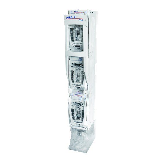
Listwowe rozłączniki izolacyjne
Vertical fuse switch disconnectors
ARS 3f;
ARS 400, ARS 2 pro, ARS 3 pro, ARS 630kVA pro, RWS 1250 pro
Instrukcja obsługi i montażu
Mounting and operation manual
ISO 9001
Manufacturing area
PN-N-18001
ISO 14001
Advertisement

Related Manuals for Apator ARS 400


Summarization of Contents
Taking Off the Cover
Take Handle to Release Position
Move the handle to the release position until it locks against the release mechanism.
Pull and Rotate Cover
Gently pull the cover ears as indicated, rotate it until resistance, then remove.
Move Handle to Operation Position
Move the handle to the 'operation/switched on' position of the disconnector.
Fixing Disconnector to Bus Bars
Open Masking Plates
Open the masking plates for fixing bolts.
Fix Disconnector to Bus Bars
Mount disconnector to bus bars with 185mm spacing and close masking plates.
Terminal Shield and Output Cables
Attach Output Cables
Remove terminal shield and tighten output cables.
Mount Terminal Shield
Mount the shield for terminals.
Mounting Fuse Links or Solid Links
Mount Fuse Links/Solid Links
Place fuse link or solid link in the cover catches.
Dismantle Fuse Links/Solid Links
Push slide element and pull out fuse link or solid link from cover catches.
Mounting Cover with Fuse Links
Insert Cover into Guide
Insert cover into the guide and rotate according to the arrow indications.
Snap Cover into Guide
Snap the cover into the guide.
Switching On the Disconnector
Switch On Disconnector
Move the handle firmly in the indicated direction until the disconnector is closed.
Switching Off the Disconnector
Switch Off Disconnector
Move the handle firmly until it blocks against the release mechanism.
Parking the Disconnector
Switch Off for Parking
Switch off the disconnector according to point 8.
Press Releases for Parking
Press the releases until the handle is released.
Pull Handle During Parking
With releases pressed, pull the handle until resistance.
Move Operating Mechanism
Grasp the operating mechanism, pull it, and move the handle as shown.
Insert Mechanism into Cabinet
Insert the operating mechanism into the cabinet until resistance to park.
Releasing the Parking of the Disconnector
Release Parking Handle
Grasp the handle and move it in the indicated direction until resistance.
Release Parking Mechanism
Press releases to free handle, then pull handle until resistance.
Insert Mechanism and Close
Insert mechanism into cabinet until resistance and close the disconnector.
Grounding the Disconnector
Remove Mechanism for Grounding
Follow point 9a,b,c,d, then remove the operating mechanism.
Mount Grounding Clamp and Ground
Mount earthing clamp, use insulating pole to ground disconnector with links.
Dismantling Earthing Switch and Mounting Operating Switch
Dismantle Earthing Switch
Dismantle the earthing switch in reverse order of point 11b.
Insert Operating Mechanism
Insert mechanism into cabinet, paying attention to guides, then close disconnector.
Connecting Outlet Cables from Top
Prepare for Cable Connection
Remove covers and terminal shield, do not lower handle.
Turn Bolts
Turn 6 bolts clockwise by 90 degrees using a screwdriver.
Remove Cabinet from Base
Take the cabinet out of the base.
Rotate and Re-insert Cabinet
Turn cabinet 180 degrees, re-insert, align bolts, and turn anticlockwise.
Prepare for Bus Bar Mounting
Disconnector is ready for bus bar mounting with top outlets.
Technical Data
Rated Thermal Current
Technical data for rated thermal current (Ith).
Rated Voltage
Technical data for rated voltage (Un).
Rated Insulated Voltage
Technical data for rated insulated voltage (Ui).
Rated Impulse Withstand Voltage
Technical data for rated impulse withstand voltage (Uimp).
Short Circuit Making Capacity
Technical data for rated short circuit making capacity.
Short-time Withstand Current
Technical data for rated short-time withstand current.
Rated Short-circuit Making Capacity
Technical data for rated short-circuit making capacity (Icm).
Short-time Withstand Current
Technical data for short-time withstand current (Icw).
Rated Frequency
Technical data for rated frequency.
Protection Degree
Technical data for protection degree (IP).
Mechanical Durability
Technical data for mechanical durability.
Electrical Durability
Technical data for electrical durability.
Size of Fuse Links
Technical data for the size of fuse links.
Safety Precautions
Use Insulated Tools
It is recommended to use insulated tools for safety reasons.
Sealing and Padlocking
Disconnector can be sealed or padlocked in switched-on or parking positions.
Material Utilization and Disposal
Proceeding with Material
Dismantle product, separate metal and plastic parts for recycling or disposal.
Transport and Storage Conditions
Storage Conditions
Store in original packaging, dry, clean rooms, specific temperature and humidity limits.
Need help?
Do you have a question about the ARS 400 and is the answer not in the manual?
Questions and answers