Table of Contents
Advertisement
Quick Links
This is an industrial component. Only a qualified systems integrator should be allowed to
design it into a system. The integrator must determine proper plumbing, mounting, driveline
and guard components.
Improper installation or use could lead to a serious, even fatal, accident. The system
integrator must communicate all safe operation procedures to the end user(s).
Before operation, fully understand and follow the instructions shown in this manual and any
instructions communicated by the system integrator. No one should be allowed to operate or
maintain this pump that has not been fully trained to work safely according to the
configuration of the pump system and in accordance with all applicable government and
industry regulations.
DO NOT paint over nameplates, ID tags or warning tags.
Confidential & Proprietary: This document contains confidential and proprietary information which is the exclusive property
of Roper Pump Company, Commerce, GA. U.S.A. and shall not be reproduced, communicated, disclosed, or disseminated in
any manner to third parties or used for any purpose other than its intended purpose without prior written consent of the
management of Roper Pump Company.
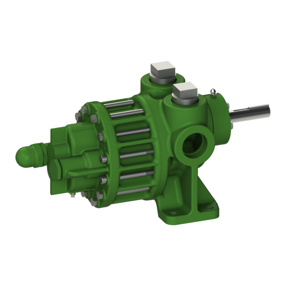
F SERIES TYPE 27
OWNERS MANUAL
SAFETY INSTRUCTIONS
Roper Pump Company
P.O. Box 269
Commerce, GA 30529 USA
Telephone: (706) 335-5551
TeleFAX: (706) 335-5490
Email:
sales@roperpumps.com
www.roperpumps.com
G12-208
06/13/16
1
Advertisement
Table of Contents

Related Manuals for Roper F20


Summarization of Contents
Warnings and General Guidelines
System Pressure and Hazardous Fluids
Guidelines for handling system pressure and hazardous or toxic fluids safely.
Plumbing
Proper installation procedures for pump plumbing to minimize losses and prevent damage.
Mounting Base
Recommendations for mounting the pump unit on a rigid and stable base.
Pump and Drive Assemblies
Requirements for installing pump and drive assemblies, including guards and codes.
Check Alignment of Pump to Driveline
Explains how to check and maintain proper pump to driveline alignment to prevent failure.
Roper Pumps' Close Coupled Drives
Details on close-coupled drive units where hydraulic or gearmotor units mount directly to the pump.
Guarding PTO Drive Shafts
Emphasizes the importance of proper guarding for PTO drive shafts for operator safety.
Nameplate Data
Figure (Model Number)
Details on the "Figure" part of the pump nomenclature, indicating mounting and relief valve.
Spec
Explains the "SPEC" designation, used for special pumps or configurations.
Type
Explains the "TYPE" number used for internal identification of construction and hydraulics.
Serial Number
Describes the unique serial number assigned to each pump for identification.
Direction of Rotations
1 & 2 F1-F100 "W" (CW) Rotations
Illustrates clockwise rotation configurations for 1 & 2 F1-F100 pump models.
1 & 2 F1-F100 "X" (CCW) Rotations
Illustrates counterclockwise rotation configurations for 1 & 2 F1-F100 pump models.
17 & 18 F10-F100 "W" (CW) Rotations
Illustrates clockwise rotation configurations for 17 & 18 F10-F100 pump models.
17 & 18 F10-F100 "X" (CCW) Rotations
Illustrates counterclockwise rotation configurations for 17 & 18 F10-F100 pump models.
17 & 18 F1-F5 "W" (CW) & "X" (CCW) Rotations
Illustrates both clockwise and counterclockwise rotation for 17 & 18 F1-F5 pump models.
1 & 2 F75-F300 "W" (CW) & "X" (CCW) Rotations
Illustrates both clockwise and counterclockwise rotation for 1 & 2 F75-F300 pump models.
Relief Valve
Relief Valve Diagram and Specifications
Detailed diagram and chart showing relief valve components and maximum extension specifications.
Mechanical Seal
Mechanical Seal Replacement for F10-F300
Details on replacing mechanical seals for pump sizes F10 through F300.
Packing
Packing Adjustment and Maintenance
Guidelines for adjusting pump packing to achieve desired leakage and prevent shaft damage.
Parts List & Cross Sectionals
1 & 2 F1-F5 SPEC 0 & 5 Diagrams
Illustrates cross-sectional views and parts for 1 & 2 F1-F5 pumps with SPEC 0 and SPEC 5.
1 & 2 F10-F20 SPEC 0 & 5 Diagrams
Illustrates cross-sectional views and parts for 1 & 2 F10-F20 pumps with SPEC 0 and SPEC 5.
1 & 2 F35-F50 SPEC 0 & 5 Diagrams
Illustrates cross-sectional views and parts for 1 & 2 F35-F50 pumps with SPEC 0 and SPEC 5.
1 & 2 F75-F100 SPEC 0, 17, 5, & 174 Diagrams
Illustrates parts for 1 & 2 F75-F100 pumps with SPEC 0, 17, 5, and 174.
1 & 2 F150-F300 SPEC 17 & 174 Diagrams
Illustrates parts for 1 & 2 F150-F300 pumps with SPEC 17 and SPEC 174.
17 & 18 F1-F5 (SPEC 0) & F10-F20 (SPEC 0) Diagrams
Illustrates parts for 17 & 18 F1-F5 (SPEC 0) and 17 & 18 F10-F20 (SPEC 0) pumps.
17 & 18 F35-F50 (SPEC 0) & F75-F100 (SPEC 0) Diagrams
Illustrates parts for 17 & 18 F35-F50 (SPEC 0) and 17 & 18 F75-F100 (SPEC 0) pumps.
Need help?
Do you have a question about the F20 and is the answer not in the manual?
Questions and answers