Table of Contents
Advertisement
Quick Links
This is an industrial component. Only a qualified systems integrator should be allowed to
design it into a system. The integrator must determine proper plumbing, mounting, driveline
and guard components.
Improper installation or use could lead to a serious, even fatal, accident. The system
integrator must communicate all safe operation procedures to the end user(s).
Before operation, fully understand and follow the instructions shown in this manual and any
instructions communicated by the system integrator. No one should be allowed to operate or
maintain this pump that has not been fully trained to work safely according to the
configuration of the pump system and in accordance with all applicable government and
industry regulations.
DO NOT paint over nameplates, ID tags or warning tags.
Confidential & Proprietary: This document contains confidential and proprietary information which is the exclusive property
of Roper Pump Company, Commerce, GA. U.S.A. and shall not be reproduced, communicated, disclosed, or disseminated in
any manner to third parties or used for any purpose other than its intended purpose without prior written consent of the
management of Roper Pump Company.
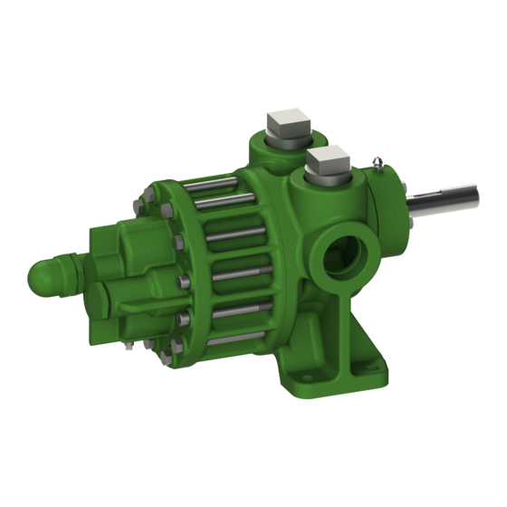
F SERIES TYPE 27
OWNERS MANUAL
SAFETY INSTRUCTIONS
Roper Pump Company
P.O. Box 269
Commerce, GA 30529 USA
Telephone: (706) 335-5551
TeleFAX: (706) 335-5490
Email:
sales@roperpumps.com
www.roperpumps.com
G12-208
06/13/16
1
Advertisement
Table of Contents


Need help?
Do you have a question about the F Series and is the answer not in the manual?
Questions and answers