Table of Contents
Advertisement
Nicotra S.p.A.- Via C.Cantù,1 – 20121 Milano – Italy
Factory.: Via Modena, 18 – Ciserano Loc. Zingonia (BG)– Italy
Factory.: Strada di Ronchis, 5 – Remanzacco (UD) - Italy
INSTALLATION AND MAINTENANCE
MANUAL
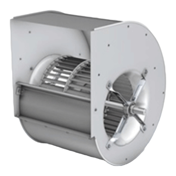
CENTRIFUGAL FANS
AT-AS-ASH-RSH-ADH-RDH
In accordance with ATEX directive
In issuing this guide-book maximum attention has been paid to ensure correct information. Nicotra S.p.A. does not accept any
responsibility for eventual errors or omissions.
Cod. 985719 – 00 / Jan 2004
Advertisement
Table of Contents

Related Manuals for Nicotra RDH


Summary of Contents for Nicotra RDH
- Page 1 CENTRIFUGAL FANS AT-AS-ASH-RSH-ADH-RDH In accordance with ATEX directive In issuing this guide-book maximum attention has been paid to ensure correct information. Nicotra S.p.A. does not accept any responsibility for eventual errors or omissions. Cod. 985719 – 00 / Jan 2004...
-
Page 2: Table Of Contents
SUMMARY 1. GENERAL INFORMATION.................. 4 1.1. ATEX VERSIONS ........................4 2. RECEIVING AND INSPECTING THE PRODUCT..........4 2.1. DATA ON THE RATING PLATE....................5 2.2. WEIGHTS OF THE PRODUCTS....................6 2.3. HANDLING AND LIFTING THE FAN ..................7 2.4. STORAGE ..........................8 3. - Page 3 6. ATEX – DECLARATION OF CONFORMITY ............. 26 ADH ATEX - OPERATING LIMITS…………………………………………………..27 RDH ATEX - OPERATING LIMITS ..………………………………………………..28 AT ATEX - OPERATING LIMITS …..……………………………………………….29 ASH ATEX - OPERATING LIMITS ..………………………………………………..30 RSH ATEX - OPERATING LIMITS …..……………………………………………..31 Cod. 985719 – 00 / July 2004...
-
Page 4: General Information
The scope of this manual is to provide information about the correct installation, use and maintenance of the fans listed in the title. The safety recommendations contained herein are of general level and can be applied to several models of Nicotra range. -
Page 5: Data On The Rating Plate
Note: for any other information, please refer always to the relevant drawing, catalogue or contact our Technical Department. 2.1. DATA ON THE RATING PLATE MOD: product description COD: Nicotra code SERIAL: serial number COD. CLI: customer code (optional) WATT MAX:... -
Page 6: Weights Of The Products
2.2. WEIGHTS OF THE PRODUCTS Approximate weights (±10%) of the standard fans, excluding the packaging, are listed in the table below. The exact weight of the fans is specified in the relevant drawing. 10/8 10/10 12/9 12/12 15/11 15/15 18/13 18/18 13,5 15,5... -
Page 7: Handling And Lifting The Fan
2.3. HANDLING AND LIFTING THE FAN The fans must be handled by experienced and fully trained staff. A wrong handling or lifting could damage the fans. The most frequent are the following: • • shifting of the wheel on the shaft due to loosening of the hub set screws •... -
Page 8: Storage
• units rotate the wheel at least once a week, to permit the redistribution of the grease inside the bearing and prevent • corrosion •... -
Page 9: Operating Temperature
3.2.3. Operating temperature The standard operating temperature is indicated in the catalogues. For short periods it is possible to use the fan at a temperature lower than –20°C, but it is dangerous to start a fan which was standing at a temperature lower than –20°C. - Page 10 • when tightening the screws, do not bend frames, fixing feet and sideplates. Avoid overloads that can compromise the correct functioning of the fan • Fix the fan on a plane base. The shaft must always be in horizontal position to avoid axial loads on bearings and anomalous vibrations.
-
Page 11: Installing The Drive System
4.2. INSTALLING THE DRIVE SYSTEM We suggest to use the selection program “Ventil” to dimension correctly type and diameter of the pulleys, belt tension etc. Pulleys should be statically and dynamically balanced with grade G4 according to ISO 1940. This is compulsory for ATEX fans. -
Page 12: Belt Tension
4.2.3. Belt tension If you do not have a specific instrument, such as a tension gauge, to measure the belt tension, you can apply the following approximate method: Proceed with the tensioning of the belts by gradual tensioning of the motor base. Correct running of the fan is determined by the correct tensioning. -
Page 13: Safety Accessories
1. If F< F', a higher belt tension is required. If F>F", the belts are too tight 2. During the running-in period of the fan belts an early decrease in tension takes place. It is therefore necessary at the initial assembly to tension the belts 1,3 times higher than the "f" arrow shown in the tables. Belt tensions should be checked regularly and always after the first eight working hours. -
Page 14: Maintenance
To guarantee smooth operation, the fan must be serviced regularly. As a general rule, complying with the operation limits and the standard working conditions, the most important maintenance measures, to be made at least twice a year, are: • •... - Page 15 A first check of the bearing can be done simply by listening to it. A normal bearing generates a smooth and uniform sound; while a damaged bearing generates a loud and irregular sound. A low metallic noise, due to standard gap between the components, is normal, especially at low speed. Excessive vibrations or temperature are often a sign of possible damages.
- Page 16 For bearings on vertical shafts the intervals obtained from the diagram should be halved. These values are not valid in presence of water, humidity or solid impurities (dust/air mixture for category 2D and 3D in case of Atex fans), which can go inside the bearings. In this case we recommend to renew frequently the whole grease. Never schedule relubrication intervals over of 30000 hours.
- Page 17 5.2.2. Mounting the bearing with eccentric locking collar Put the bearing into the rubber damper. Mount the bracket around the rubber. For AT fan it is possible to insert bearing+rubber with bracket already assembled and mounted on the sideplate, after having greased the rubber to insert it more easily Carefully clean the shaft.
- Page 18 Remove the nut and the locking washer from the adapter sleeve (fig.2) Insert the sleeve at the marked position on the shaft (fig.1,3) Slide the plummer block unit up on the adapter sleeve with the large end of the tapered bore leading Insert the locking washer and screw the lock nut on to the adapter sleeve using the proper wrench according to the tightening torque indicated in the table(fig.4)
- Page 19 If the bearing is mounted on an adapter sleeve, determine the position of the housing. The grease nipple arranged at one side of the housing cap (for improved lubrication) should be always positioned at the side opposite to the sleeve nut.
- Page 20 If a sleeve with metric thread is used, tighten the nut through the angle 75° using a hook spanner Re-position the spanner at 180° to its original position and tighten the spanner a few degrees more by tapping the spanner handle lightly with a hammer.
- Page 21 Put the locating ring(s) (when needed, better transmission side) at each side of the bearing Carefully align the housing base. Vertical markings at the middle of the side faces and ends of the housing base can facilitate this. Then lightly tighten the attachment bolts Cod.
- Page 22 The remaining seal halves should be inserted in the seal grooves in the housing cap and the space between the sealing lips filled with grease The housing cap should be placed over the base and the cap bolts (to join cap and base) tightened to the torque according to the table.
- Page 23 SKF ConCentra units and other components. Then proceed as described under points 5 to 5.2.10. Mounting ConCentra roller bearing Determine the positions of the locating and non-locating units. The locating unit should always be at the drive side Mount any components which are to be on the shaft between the bearing positions Push the bearing units on to the shaft with dismounting side leading.
- Page 24 1,5°. Fully tighten the attachment bolts of the non-locating bearing unit. The recommended tightening torques are given under point 10. If needed at the end of the shaft, snap the end cover into the housing bore. Cod. 985719 – 00 / July 2004...
- Page 25 LUBRICATION SKF ConCentra roller bearing units are delivered filled with SKF grease LGEP 2. The quantity of grease corresponds to a completely filled bearing free space housing. Relubricate the unit with SKF grease LGEP 2 or equivalent. The quantity of grease for relubrication is 15 g. LABEL The designation of the unit is shown on a label covered by a transparent protective film.
- Page 26 La documentazione tecnica di riferimento del prodotto, come previsto dalla Direttiva 94/9/CE allegato VIII, è disponibile presso la Nicotra S.p.A. di Via Modena,18 Ciserano Loc Zingonia e per i ventilatori della categoria 2 la stessa è stata depositata presso l’ente notificato LCIE (0081) con numero ATEX/ITA/04/063.
- Page 27 rev. 11 ADH "ATEX" - LIMITI DI IMPIEGO - OPERATING LIMITS 900 1000 18,5 Potenza max. da installare 18,5 18,5 18,5 18,5 Max. installed power 18,5 Max. Antriebsleistung Puissance max. applicable G2L-G2R Potencia max. a instalar 18,5 18,5 G2K2 4200 4000 3800 3400...
- Page 28 rev.11 RDH "ATEX" - LIMITI D'IMPIEGO - OPERATING LIMITS 900 1000 Potenza max. da installare 18,5 18,5 18,5 18,5 Max. installed power Max. Antriebsleistung Puissance max. applicable Potencia max. a instalar G2K2 18,5 18,5 6800 6000 5800 4100 4000 3500 3300 2700 2500...
- Page 29 AT "ATEX"- LIMITI DI IMPIEGO - OPERATING LIMITS 10/8 10/10 12/9 12/12 15/11 15/15 18/13 18/18 20/15 20/20 22/15 22/22 25/20 25/25 28/20 28/28 30/20 30/28 Potenza max. da installare Max. installed power 11,0 11,0 11,0 11,0 15,0 15,0 Max.
- Page 30 rev.11 ASH "ATEX" - LIMITI DI IMPIEGO - OPERATING LIMITS 1000 Potenza max. da installare Max. installed power 18,5 18,5 18,5 Max. Antriebsleistung Puissance max. applicable 18,5 Potencia max. a instalar 3800 3400 3000 2700 2400 2100 1900 1600 1300 1200 1100 Velocità...
- Page 31 rev.11 RSH "ATEX" - LIMITI D'IMPIEGO - OPERATING LIMITS 1000 Potenza max. da installare Max. installed power Max. Antriebsleistung 18,5 Puissance max. applicable Potencia max. a instalar 18,5 4600 4100 3600 3300 2800 2500 2200 2000 Velocità Max 4600 4100 3600 3300 2800...
Need help?
Do you have a question about the RDH and is the answer not in the manual?
Questions and answers