
Related Manuals for Nicotra EC FAN FDP


Summary of Contents for Nicotra EC FAN FDP
- Page 1 EC FAN FDP OPERATING MANUAL Regal Beloit Italy S.p.A. Via Modena, 18 24040 Ciserano (BG) ITALY Phone +39 035 873 111 Fax +39 035 884 319 www.regalbeloit.com Rev. 0 - 11/12/2020...
-
Page 3: Table Of Contents
OPERATING MANUAL OPERATING MANUAL INDEX INDEX DEFINITIONS AND WARNINGS ..............................5 1.1 Object of this manual .................................5 1.2 Symbols used ..................................5 1.3 Qualified personnel ................................5 1.4 Use for intended purpose only ............................5 1.5 Safety instructions ................................6 1.6 Informative letter ................................7 1.7 Safe operating area................................7 REGULATORY REFERENCES ..............................8 2.1 Mechanical and electrical safety ............................8 2.2 Electro-Magnetic Compatibility (EMC) ..........................8 DATA PLATE .....................................9 TRANSPORT AND STORAGE ..............................10 PACKING CONTENTS ................................10 UNPACKING ...................................11 PRODUCT DESCRIPTION ...............................11... - Page 4 OPERATING MANUAL OPERATING MANUAL 10.2.1 Analog asynchronous emulation ........................... 24 10.2.2 Modbus temporary asynchronous emulation ....................... 24 10.2.3 Modbus fixed asynchronous emulation ......................... 24 10.2.4 Asynchronous emulation curves: examples ......................25 10.3 PID closed control loop ..............................25 10.3.1 Modbus temporary ref. PID closed control loop ....................25 10.3.2 Modbus fixed ref. PID closed control loop ......................25 10.3.3 Modbus positive/negative feedback ........................26 10.4 Changing the operation mode ............................26 OTHER FEATURES ..................................26 11.1 Filter alarm ..................................26 11.2 Soft start ..................................27 SOA LIMITATIONS .................................27 12.1 Speed limitation ................................27 12.2 Power limitation ................................27 12.3 Output current limitation ...............................
-
Page 5: Definitions And Warnings
Danger to persons due to electricity. The operations whose execution requires qualified or specialized staff to avoid any danger are indicated with this symbol. 1.3 Qualified personnel For this Instruction Manual and product labels, a "Qualified person" is someone who is familiar with the installation, mounting, start-up and operation of the equipment and the hazards involved. He or she must have the following qualifications: • Trained and authorized to energize, de-energize, clear, ground and tag circuits and equipment in accordance with established safety procedures. • Trained in the proper care and use of protective equipment in accordance with established safety procedures. • Trained in rendering first aid. 1.4 Use for intended purpose only The equipment may be used only for the application stated in the manual and only in conjunction with devices and components recommended and authorized by Nicotra Gebhardt. 5/40 Rev. 0 - 11/12/2020... -
Page 6: Safety Instructions
This manual is an integral part of the EC Fan FDP and it must be carefully read before using it since it gives important indications with regards to its safe installation, use and maintenance. Keep it with care. -
Page 7: Informative Letter
The content of this guide can be modified without prior notice. Great care has been taken in collecting and checking the documentation contained in this manual to make it as complete and comprehensible as possible. Nothing contained in this manual can be considered as a warranty, either expressed or implied - including, not in a restrictive way, the suitability warranty for any special purpose. Nothing contained in this manual can be interpreted as a modification or confirmation of the terms of any purchase contract. Nicotra Gebhardt products have not been conceived to work in areas at risk of explosions. In case of damage or mal- function, the FDP fans must not be used until the Customer Care Technical Service has repaired it. Customer Care Technical Service For information concerning the nearest supporting center, please get in touch with your retailer. WARNING WARNING The original configuration of the fan must not be changed at all, except as prescribed in this manual. -
Page 8: Regulatory References
60335-1 “Household and similar electrical appliances - Safety - General requirements” and 60335-2-40 “Household and similar electrical appliances - Safety - Particular requirements for electrical heat pumps, air-conditioners and dehumidifiers”. Such safety requirements are covered as far as necessary for a partly complete machine, sub-assembly or component, as these fans are specifically intended for incorporation within other machines. The responsibility for the mechanical and electrical safety of the installed fan is thus of the manufacturer of the complete machine and, for this reason, it is strictly forbidden to put the fan in operation before the manufacturer of the machine has assessed and declared that the complete machine fulfils all the essential safety requirements set forth by the MD. Please, check the Declaration of Incorporation which accompanies each product, or ask your Nicotra Gebhardt sales representative, for additional information. 2.2 Electro-Magnetic Compatibility (EMC) Single-phase drive systems: FDP 1 kW, The drivers of these products incorporate an Active Power Factor Control module, to provide harmonics filtering and compliance with the EMC requirements applicable to domestic and equivalent environments (“first environment”), or with the advanced re- quirements for harmonic distortion which often apply to data centers. -
Page 9: Data Plate
OPERATING MANUAL OPERATING MANUAL To improve the Electromagnetic compatibility a ferrite should be put on the power supply cable (close to the driver). The compliancy to the standards is intended for a single fan. No tests have been made on multiple installations. The compliancy to the standards are intended for a single fan. -
Page 10: Transport And Storage
OPERATING MANUAL OPERATING MANUAL 4. TRANSPORT & STORAGE WARNING WARNING Correct transport, storage, erection and mounting, as well as careful operation and maintenance are essential for proper and safe operation of the equipment. Protect the fan against physical shocks and vibration during transport and storage. Also, be sure to protect it against water (rainfall) and excessive temperatures. -
Page 11: Unpacking
OPERATING MANUAL OPERATING MANUAL 6. UNPACKING Remove the fan from the box. Remove all the components from the packaging. WARNING WARNING Check the fan. Before installing the FDP fan, check to ensure that all of the items listed are present and that there are no visible signs of damage. Dispose of all packing components in compliance with the laws in force in the country of use. RECYCLE 7. -
Page 12: Technical Features
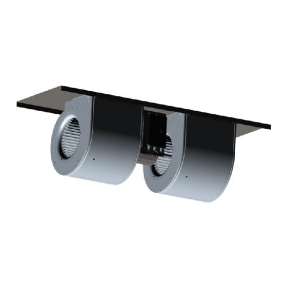
OPERATING MANUAL OPERATING MANUAL General Features • Sensorless control • Simple installation due to plug and play • Designed for double inlet fans Interface • Analogue interface for speed control • Full MODBUS interface com- pliancy High efficiency of direct driven centrifugal fan • Integrated solution • Top rating efficiency • Plug and play operation • No need to configure long lists of inverter parameters •... -
Page 13: Dimensional Drawings
OPERATING MANUAL OPERATING MANUAL 8.1 Dimensional drawings The plate dimensions and the anchor points can be different. 6N4406 - FDP 180/240 Z 1413G6 6N4407 - FDP 200/190 N 1413G6 6N4408 - FDP 200/190 N 1413H3 13/40 Rev. 0 - 11/12/2020... - Page 14 OPERATING MANUAL OPERATING MANUAL 6N4404 - FDP 200/240 N 1413H4 6N4405 - FDP 200/240 N 1413H3 6N4409 - FDP 9/7A 1413H3 6N4410 - FDP 9/9A 1413H3 14/40 Rev. 0 - 11/12/2020...
-
Page 15: Motor - Driver Connections
In the standard arrangement of the FDP fan, the motor is turning clockwise when seen from the cable-entry side, and the electrical connections of the motor cable to the driver board are made as shown in the following figure. The actual position of the motor connections on the printed circuit board may differ, between different driver models. WARNING WARNING These connections are carried out by Nicotra Gebhardt and cannot be modified by the end user. 9. INSTALLATION The fan installation must be carried out only by competent and qualified staff. WARNING WARNING In the final installation, the device shall be directly connected to the supply terminals and shall have a contact separation in all poles, providing full disconnection under overvoltage category III conditions. -
Page 16: Operation
OPERATING MANUAL OPERATING MANUAL 9.2 Operation WARNING WARNING The driver must NOT be removed from the related FDP fan type and size. The driver cannot be used separate from the related fan. WARNING WARNING Ensure correct grounding connections. The ground cable must be enough to carry the maximum supply fault current which nor- mally will be limited by the fuses or MCB. -
Page 17: Electrical Connections
OPERATING MANUAL OPERATING MANUAL 9.5 Electrical connections FDP 1.05kW 1-Phase REF. DESCRIPTION Power supply Control board connection Communication Blinking LED Relay connection Make sure that a differential switch (circuit breaker) has been installed upstream the line and that it functions properly. Before carrying out any intervention on the electrical system, disconnect the power supply by means of main switch. WARNING WARNING Work on the driver/fan by unqualified personnel or failure to comply with warnings can result in severe personal injury or serious... -
Page 18: Power Supply
OPERATING MANUAL OPERATING MANUAL 9.5.1 Power supply The end user must connect the power supply cable and the command signal to the control board, while the motor connection is already done by Nicotra Gebhardt. As concerns the cable minimum section, check the requirements issued by the country of installation. FDP 1.05kW 1-Phase Single Phase 220/240V ±10% @ 50/60Hz The performance in the range [200V-264V] @ 50Hz/60Hz is always the same due to the PFC module inside the driver. Min. and max. wire section: Spring-loaded push-in clamp, suitable for •... -
Page 19: Connection Details
The driver may be damaged or not functioning properly. The available +10V power supply of the driver is intended to be used with a potentiometer of minimum 2KOhm, with a max absorbed current of 5mA. Any different devices connected to it could bring to an undesired functioning of the driver or of connected device. Nicotra Gebhardt can provide a dedicated potentiometer: REGPOT code K43138. 19/40 Rev. 0 - 11/12/2020... - Page 20 OPERATING MANUAL OPERATING MANUAL If two or more fans are installed in the same compartment and operated in parallel, the fans must start and stop at the same time. An auto-restarting alarm occurs when a fan is forced to run forward (or backward) rotation with a speed higher than 150 rpm. If an ext. 4-20mA device is used, it is necessary to add 0.1% precision resistances between the ANALOG INPUT and GND. The value of the resistance can range from: 125 Ω -> V ranges from 0.5V to 2.5V signal to 500 Ω -> V ranges from 2V to 10V signal 20/40 Rev. 0 - 11/12/2020...
-
Page 21: Modbus Communication
OPERATING MANUAL OPERATING MANUAL 9.5.3.2 Modbus Communication A Modbus RTU protocol is available on all the fan models. The line must be connected to MODBUS-A, MODBUS-B and GND pins. There are two possible Modbus connections: 1) During the fan functioning through any RS-485 serial connection 2) With the driver powered off through an UART serial connection To connect the driver to a PC during the fan functioning, a USB to 485 converter can be used: K431F8. To connect OFFLINE the driver to a PC when the fan is powered off, a USB to UART converter can be used: K431A6 for 1-phase drivers. A MOLEX connector "1" is used to connect the cable to the driver. 1-phase Specifications and drivers can be downloaded from Nicotra Gebhardt website: https://www.nicotra-gebhardt.com 21/40 Rev. 0 - 11/12/2020... -
Page 22: Tachometric, Alarm And Filter Output
OPERATING MANUAL OPERATING MANUAL 9.5.3.3 Tachometric, Alarm and Filter Output The analogue output channel is configured, by default, to provide a tachometric output signal. The tachometric output is a 0 to 5V PWM waveform at 1KHz (for FDP 1.05kW -1-Ph only). when the speed is equal or higher than the speed min and it is 0% when the speed is lower. The device reading the output must be connected to TACHO\ALARM\FILTER pin and GND. The max current supplied of the output is 0.2mA. Remember that the Speed is 0 whenever the required speed is lower than Speed unless the fan is in the dragging Real phase. The same analogue output channel can be reconfigured, by changing the value in Holding Register 46 (see paragraph 16.3 at page 34), as a Digital Alarm Output (refer to chapter 17 and paragraph 17.4), or in one of the alternative alarm modes described in pa- ragraphs 11.1 and 11.2. -
Page 23: Speed Control
OPERATING MANUAL OPERATING MANUAL 10.1 Speed control 10.1.1 Analog speed control (INPUT TYPE = 1 Default factory setting) Through this setting the fan speed is proportional to the analog voltage input. The fan speed is limited by the Safe Operating Area, therefore, depending on the fan working point, the fan could be no more able to increase the speed coherently to the set voltage value. To avoid the loss of signal dynamic, a speed limit rescaling is necessary by modifying the value of the Max Speed Holding Register 2. It is also possible to rescale the min Speed by modifying the Holding Register 1. The analog signal can be read from the Input Register 14. For more details refer to the ANNEX -> Analog Signal Considerations. The MAX and min speed default values are in function of the fan sizes. -
Page 24: Speed Control Curves: Examples
OPERATING MANUAL OPERATING MANUAL 10.1.4 Speed control curves: example The following figures show a set of performance curves at different speed settings limited by the fan max working limit curve (see paragraph 1.6). 10.2 Asynchronous emulation Through this mode there is the possibility to emulate the behavior of an asynchronous induction motor with a slip and a power limitation dependent on the load and speed (therefore there could be some differences from each size). The control is expressed in percentage instead of a defined measure unit. The lower is the slip the higher is the performance and vice versa. 10.2.1 Analog asynchronous emulation (INPUT TYPE = 7) Through this setting the slip is proportional to the analog voltage. 10.2.2 Modbus temporary asynchronous emulation (INPUT TYPE = 8) Through this setting the fan emulates an ACIM motor and the slip is defined by modifying the Holding Register 66. The setting is maintained meanwhile the fan is powered on and it is lost when the fan is powered off. 10.2.3 Modbus fixed asynchronous emulation (INPUT TYPE = 9) Through this setting the fan emulates an ACIM motor and the slip is defined by modifying the Holding Register 30. -
Page 25: Asynchronous Emulation Curves: Examples
OPERATING MANUAL OPERATING MANUAL 10.2.4 Asynchronous emulation curves: example The following figures show 5 curves with the following slip percentage: 100%, 80%, 60%, 40% and 20%. The slip has not a physical meaning and must be intended as a 100% full performance and 0% fan stop. 10.3 PID closed control loop 10.3.1 Modbus temporary ref. PID closed control loop (INPUT TYPE = 11) In this mode the PID reference is defined by modifying the Holding Register 66. -
Page 26: Modbus Positive/Negative Feedback
OPERATING MANUAL OPERATING MANUAL 10.3.3 Modbus positive/negative feedback Depending on the application it could be necessary to invert the feedback behavior. Through the Holding Register 31 it is possible to multiply by -1 the PID The probe voltage error. decreases When the register is set to 0 -> Error = (R eference easure When the register is set to 1 -> Error = (M The probe voltage easure eference Increasing the fan speed decreases 10.4 Changing the operation mode Here are shown the actions passing from one operation mode to another one. ACTION ACTIONS A ACTIONS B Temporary Setting The fan must follow the target corresponding to the value... -
Page 27: Soft Start
OPERATING MANUAL OPERATING MANUAL 11.2 Soft start In the following paragraph the starting phase of a fan is shown. • The first phase when the fan receives a command to start running is the ALIGNMENT. During this phase the driver aligns the rotor. • The second phase is the dragging phase, where the fan gradually increases its speed to the minimum in open loop. In this phase the current and speed values present in the Input Register can’t be taken in consideration. • The last phase is the closed loop where the sensorless control is active and from the minimum speed to the target speed the fan accelerates with different ramps basing on the fan size and the wheel inertia. The acceleration and deceleration values are different and to avoid overvoltage alarm or loss of synchronism alarm, the deceleration is always lower. During the ALIGNMENT and DRAGGING phases a Loss of Synchronism alarm could occur if there is a condition of wrong rotor starting position or wrong position estimation during the open loop phase. This is not a blocking alarm; therefore the fan stops and auto-restarts after few seconds. -
Page 28: Other Variables
OPERATING MANUAL OPERATING MANUAL 13. OTHER VARIABLES There are other variables that can be monitored for a safe use of the fan. 13.1 Bus voltage The BUS voltage is the DC voltage on the bus capacitors. The driver is continuously monitoring this voltage and will stop the motor in the event of under-voltage or over-voltage. The value can be monitored through the Input Register 9. 13.2 Motor voltage The motor voltage is the peak value of the phase voltage module. To know the rms line to line value, it must be multiplied by √3/2. The value can be monitored through the Input Register 13. 14. DERATING AND OVERHEATING PROTECTIONS 14.1 Driver overheating: DERATING When the temperature of the driver components overtakes a defined temperature threshold, the performance is automatically reduced to decrease the heating. It is possible to check in real time the temperature by reading the Input Register 15. If it is not possible to reach a steady thermal equilibrium, the driver shuts down. The protection acts limiting the current to the motor. In this condition the driver goes in alarm (see chapter 17). Once the temperature on the driver decreases under 75°C, the alarm is automatically reset. 14.2 Motor overheating: THERMAL PROTECTOR The motor is protected through one or more Thermal Protectors. If the motor temperature is too high, the thermal protector opens one phase and the driver recognizes the error and stops the fan (see chapter 17). -
Page 29: Master & Slave Mode
OPERATING MANUAL OPERATING MANUAL 15. MASTER & SLAVE MODE A Master & Slave connection is necessary when the fans have to operate in parallel and in any Constant-Airflow mode, or under control of the internal PID regulator. Having two or more fans self-controlling independently, while operating in parallel, can make the system unstable. A Master & Slave connection is neither needed nor recommended when the fans in parallel are runnig in any speed-control mode, even if under control of a common external PID regulator. MASTER SLAVE MASTER SLAVE 15.1 Master and Slave 0-5V PWM out (for 1.05 kW 1-phase only) This single-phase driver has a tachometric output ranging from 0 to 5V and a special configuration must be set on the slave fan for a Master&Slave connection. It is possible to drive two fans in a master and slave configuration by setting the MASTER in any preferred mode and the SLAVE in Master&Slave mode only. The SLAVE operating mode must be changed (INPUT TYPE = 3). The MASTER must have the Holding Register 46 set at 0 = TACHO. 16 COMMUNICATION When trying to enter a value in any holding register, the value is not overwritten if the new value is outside the load boundaries. - Page 30 OPERATING MANUAL OPERATING MANUAL Supported Function: Read Holding Registers Read Input Registers Write Single Holding Register Modbus Communication Timeout With this feature it is possible to stop the fan when the communication is lost, after a period of time set in the Holding Register 56. The register can be set to: No Communication Timeout Time expressed in seconds, therefore it is possible to set 1 to 32767 from 1sec to 9h 6m 8 sec When the timeout occurs, the driver goes in alarm condition and the communication must be restored and the alarm must be cleared. The alarm is indicated in the Input register 17 with the value of 255 (0xFF).
-
Page 31: Temporary Holding Register
OPERATING MANUAL OPERATING MANUAL 16.1 Temporary holding register The Holding Register 66 is a special register used in each operating mode for setting the speed, the airflow, the slip and the PID reference. It is not a physical register and it can be written, but it is not possible to read its value. The setting remains active until the fan is powered on. If the fan is powered off but there is a residual charge, the microcontroller of the driver is still functioning. Therefore, if it is powered on in this situation the value set through the register 66 is still active. 16.2 Fixed holding register The drivers Holding Registers permanently stored into the EEPROM are 64, but only 26 registers are modifiable by the end user (see the table in the following page). - Page 32 OPERATING MANUAL OPERATING MANUAL Holding Register 0: RESET [Adim] This register can be used to reset the fan by writing the value 1 on it. This register automatically retun to value 0 after being reset. The driver will reset any error condition and it will try to restart. Allowed values = 0 and 1 Default value = 0 Holding Register 1: Min Speed [RPM] This register is used to set the minimum speed of the fan. Allowed values = [Default Value, Max Speed] Default value = table below 200/190 200/240 200/190 180/240 200/240 1413H3 1413H3 1413H3 1413H3 1413G6 1413G6 1413H4 1.05kW 1-Phase...
- Page 33 OPERATING MANUAL OPERATING MANUAL Holding Register 30: Asynchronous Slip. [%] This register can be used to set the slip of an emulated ACIM motor. The register is active when the Input Type Holding Register is set to the value 9. Allowed values = [0, 100] Default value = 0 Holding Register 31: PID Positive/Negative [Adim] This register can be used to invert the feedback behavior of the PID. Allowed values = 0 and 1 Default value = 0 Holding Register 32: Avoid Range Start [RPM] This register combined with the Avoid Range End can be used to skip some resonance frequencies of the fan. Allowed values = [0, Avoid Range End] Default value = 20000 Holding Register 33: Avoid Range End [RPM] This register combined with the Avoid Range Start can be used to skip some resonance frequencies of the fan.
- Page 34 OPERATING MANUAL OPERATING MANUAL Holding Register 36: Maximum Power [W] This register can be set to reduce the power out to the motor. Allowed values = [10, Default Value] Default value = table below Value 1.05kW 1-Phase 1050 Holding Register 39: Constant Airflow [m3/h] This register can be used to set the constant airflow value. The register is active when the Input Type Holding Register is set to the value 6. *This setting is not currently available. If necessary, contact Regal Beloit Italy S.p.A. Allowed values = [Min Airflow, Max Airflow] Default value = 0 Holding Register 45: Modbus Address [Adim] This register can be used to change the Modbus address of a driver.
- Page 35 OPERATING MANUAL OPERATING MANUAL Holding Register 48: Modbus Stop Bits [Adim] (Default = 0) This register can be used to set the parity and the stop bits. Allowed values = table below Default value = 0 2 Stop Bits/No Parity 1 Stop Bit/Even Parity 1 Stop Bit/Odd Parity Holding Register 50: External Set [10 −1 This register can be used to set the reference of the PID control. Allowed values = [0, 100] Default value = 0 The register is active when the Input Type Holding Register is set to the value 12. Holding Register 51: Kp [Adim] This register can be used to set the Proportional Gain of the PID control.
-
Page 36: Input Register Description
OPERATING MANUAL OPERATING MANUAL Holding Register 56: Communication Timeout [s] This register can be used to set a timeout period for the communication. Allowed values = [0, 9hour 8min 8sec] Default value = 0 At the end of the period set into the register the fan stops and there is an Alarm indication. To restart a reset command must be sent. Communication Timeout =0 means that it is DEACTIVATED 16.4 Input register description The Modbus Input Registers are in total 33, but only 14 are useful for the end user. Speed Reference [rpm] Module Temperature °C] Measured Speed [rpm] Alarm 2 [Adim] Bus Voltage Enable Input [10/2 Alarm 1 [Adim] Analog Input [10/2 Motor Current [mA] Transducer Input [10/2... -
Page 37: Fan Info And Modbus Registers
OPERATING MANUAL OPERATING MANUAL Input Register 17: Alarm 2 [Adim] This register must be combined with the Alarm1 register. Input Register 28: Enable Input [Adim] This input indicates the ENABLE state. The value must be multiplied by 10V/2 to have the corresponding voltage value. Input Register 29: Analog Input [Adim] This input indicates the Reference Value. The value must be multiplied by 10V/2 to have the corresponding voltage value. Input Register 30: Transducer Input [Adim] This input indicates the Transducer Value. The value must be multiplied by 10V/2 to have the corresponding voltage value. Input Register 31: Measured Power [W] This register indicates the absorbed power. -
Page 38: Alarm Handling
OPERATING MANUAL OPERATING MANUAL 17. ALARM HANDLING When a malfunctioning occurs, the driver has two possible behaviors depending on the cause of the alarm: The cause of the alarm is very dangerous -> The driver stops immediately. To restart the fan, once the BLOCKING problem has been corrected, it is necessary to reset the fan or power the driver off for 5 minutes. The cause of the alarm is contingent to a wrong setting or wrong working condition. The alarm indica- AUTO-RESTARTING tions are activated, but after some seconds the fan tries to restart automatically. 17.1 Monitoring The alarms can be monitored through three different ways: • Modbus Registers • Blinking LED • Digital Output 17.2 Modbus registers - Alarm description In the following table, the alarms and the values stored in the related Modbus Input Register 10 and Input Register 17 are indicated. Alarm 1 Alarm 2 Description Actions... -
Page 39: Digital Alarm Output
Temporary 0, 5, 8, 11 Register 0 set to 1 The Holding Register 0 is a general reset and works also in the Analog mode and Fixed mode. 18. AVAILABLE SOFTWARE A freeware software is available on Nicotra Gebhardt site (http://www.nicotra-gebhardt.com) for monitoring the fan. Please refer to the related manual for more details WARNING WARNING The software can be used for configuring the fan and monitoring the performance. - Page 40 OPERATING MANUAL OPERATING MANUAL Regal Beloit Italy S.p.A. Via Modena, 18 24040 Ciserano (BG) ITALY Phone +39 035 873 111 Fax +39 035 884 319 www.regalbeloit.com 40/40 Rev. 0 - 11/12/2020...
Need help?
Do you have a question about the EC FAN FDP and is the answer not in the manual?
Questions and answers