Table of Contents
Advertisement
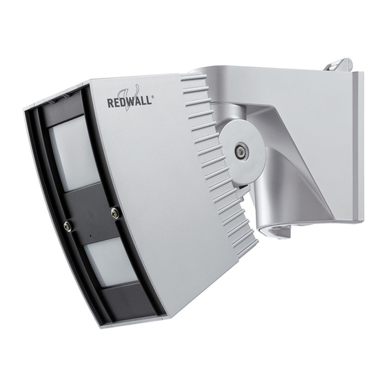
INSTALLATION INSTRUCTIONS
Synthesized Intelligent PIR
Synthesized Intelligent PIR
REDWALL-V series
REDWALL-V series
FEATURES
* Intelligent PIR Detection System
- Detection of ambient temperature and illuminance for
automatic sensitivity management
- Advanced detection algorithm
- Three dual pyro-elements with patented Double Conductive
Shielding
* Anti-vandalism functions
- Anti-rotation function with accelerometer
- Anti-masking function with photo-beam
- Reinforced polycarbonate housing
- Max. 4 m (13 ft.) installation height
*
n I
d
e
p
e
n
d
e
t n
s
e
n
i s
v i t
y t i
s
e
e l
* Detection logic selector
* Detection range selector
* Independent N.C. and N.O. outputs
* Adjustable alarm interval time
• SIP-3020CAM DN (EU), SIP-3020CAM DN (US)
*
H
g i
h
q -
u
l a
y t i
c
a
m
e
a r
i
m
a
g
: e
* 480 TV lines
* Varifocal lens 3-9 mm
REDWALL-V
: Synthesized Intelligent PIR
•
SIP-3020
•
SIP-4010
•
SIP-404
* UL/c-UL Listed
1
PARTS IDENTIFICATION
Base
Main unit
Fixing screw
for the base
Adjustment screws
(two facing each other)
Angle adjustment guide
Arrow marking
Fixing screw
No. 59-1494-6 1710-11
No. 59-1494-6 1710-11
UL
c
o t
f r
r o
n
e
a
f / r
r a
a
e r
a
s
D
a
y
c (
o
o l
u
) r
N /
g i
h
( t
/ B
W
)
REDWATCH-V
: Synthesized Intelligent PIR
with D/N camera
•
SIP-3020CAM DN (EU)
•
SIP-3020CAM DN (US)
* UL-1: SIP-3020CAM DN (EU) and
-3020CAM DN (US) are not listed by UL
Far area mirror
Masking plate for far area
Fixing rubber form
Window
Fixing rubber
Fixing screw
form (*1)
for the cover
Masking plate for near
Cover
area (*1)
Near area mirror
*1: Not used for the SIP-4010 and SIP-404.
SIP-3020CAM DN
Camera unit
2
INSTALLATION AND MAINTENANCE NOTES
Failure to follow the instructions provided
Warning
with this indication and improper handling
may cause death or serious injury.
Failure to follow the instructions provided
Caution
with this indication and improper handling
may cause injury and/or property damage.
The check
mark indicates recommendation.
The nix
sign indicates prohibition.
Warning
Never repair or
modify product
Nylon wire
loop
When servicing, the sensor
can be hooked onto the base
using the nylon wire loop.
2-1
INSTALLATION HINTS
2.3-4.0 m
(7.6-13 ft.)
The detection zones of Redwall-V and Redwatch-V, which may be
cause of false alarms can be eliminated by masking.
1. To confirm detection zones
Use optional Area View Finder, AVF-1
2. To eliminate unnecessary detection zones
a. Use supplied area masking seals.
b. Use equiped area masking plates.
The following shows an example;
Detection zones and related segments of the mirror of SIP-3020.
See step 4 and 6.
REDWALL-V SIP-3020
* SIP-4010 and SIP-404 do not have a
masking function.
FAR
NEAR
Area View Finder
3020 (521203)
1 2
4 5 6 7
B6
B1
B3
B4
B2
B5
C2 C3 C4
C1
C5
C6
D1
D6
D
3
D
4
D2
D5
E1
E6
E2 E3 E4
E5
F1
F6
F
2
F
3
F
4
F
5
* UL-2: SIP-3020, -4010 and -404 are recommended not to be connected to an alarm initiating
circuit but may be connected to a trouble alarm circuit if nuisance trips are not tolerable.
- 1 -
Caution
Hold the main unit
securely when you
install or service it.
If you remove your
hands from the main
unit when cables are
connected to it, the
main unit may fall
and the connector
cables may break
or the circuit board
may be damaged.
Caution
Verify that the
power is off before
connecting the
wiring.
Mount the detector so that the majority of
traffic flow is across the detection pattern.
1
2
3
4
5
6
7
B1
B2
B3
B4
B5
B6
C1
C2
C3
C4
C5
D1
C6
D2
D3
D4
D5
E1
D6
E2
E3
E4
E6
E5
F1
F2
F3
F4
F5
F6
Area Masking Seals
6
4
2
5
F 6
F 4
F 2
F 5
F
E
E 6
E 4
E 2
E 5
D
D 6 D 4 D 2
D 5 D 3 D 1
C
C 6 C 4 C 2
C 5 C 3 C 1
B
B 6
B 4
B 2
B 5
3
1
F 3
F 1
E 3
E 1
B 3
B 1
Advertisement
Table of Contents

Related Manuals for Redwall SIP-404


Summary of Contents for Redwall SIP-404
- Page 1 • SIP-404 • SIP-3020CAM DN (US) The detection zones of Redwall-V and Redwatch-V, which may be * UL/c-UL Listed * UL-1: SIP-3020CAM DN (EU) and cause of false alarms can be eliminated by masking. -3020CAM DN (US) are not listed by UL 1.
-
Page 2: Installation And Angle Adjustment
INSTALLATION AND ANGLE ADJUSTMENT Wall Mounting Inside View of the Base Attach the paper template (an accessory) onto the wall, Base Main unit connector Waterproof seal and drill a 6-mm dia. mounting hole and a cabling hole. Wall mounting hole (Do not remove Insert the anchor bolt (an accessory) into the board mount this seal.) - Page 3 Adjust the angle of the main unit in a horizontal direction so Power wires should not exceed the following lengths. that you can cover the desired detection area. SIP-3020CAM DN (EU) SIP-3020/SIP-4010/SIP-404 SIP-3020CAM DN (US) WIRE SIZE Rotate the main unit. 12V DC 14V DC 24V AC...
- Page 4 (OPM-WT) (AWT-3) For all areas For near area For near area For far area For far area Use at “REDWALL” Power selector Use at “REDWALL” Power selector Fine adjust the main unit angle in vertical and horizontal position. switch position.
-
Page 5: Function Setting
Detection Logic Selector Switch Cautions>> Dip switch When you are checking the detection area, take care not SIP-3020 SIP-4010 SIP-404 SIP-3020CAM DN to cover the shaded area of the window with the walk Applicable models tester or its cable. If infrared beams to the sensor are The near area sensor has two dual-element partially shielded, the detection sensitivity will drop and devices, and it covers two types of plane areas... -
Page 6: Detection Area
DETECTION AREA Applicable Applicable SIP-3020 SIP-4010 SIP-404 SIP-3020CAM DN SIP-3020 SIP-4010 SIP-404 SIP-3020CAM DN models models TOP VIEW TOP VIEW [ft.] (Installation height 4.0 m (13ft.)) [ft.] (Installation height 4.0 m (13ft.)) [ft.] SIDE VIEW (Installation height 4.0 m (13ft.)) : Near area : Far area 40 [m]... -
Page 7: Top View
Masking the Far Area Sensor The far area mirror mounted in the main unit has 2 far masking Applicable SIP-3020 SIP-4010 SIP-404 SIP-3020CAM DN plates; one at the right side of this mirror and the other at the left models TOP VIEW (Installation height 4.0 m (13ft.)) [ft.]... - Page 8 MASKING THE NEAR AREA SENSOR Applicable SIP-3020 SIP-4010 SIP-404 SIP-3020CAM DN Masking the Detection Areas using models Masking Plates Remove the masking plate from the storage, and check the detection Attach the masking plate to the mirror, area and the mirror you use by The near area mirror mounted in the main unit has 2 near and secure it to the ribs.
- Page 9 ADJUSTMENT OF CAMERA Adjustment of Camera Masking the Detection Areas using Masking Seals Applicable SIP-3020 SIP-4010 SIP-404 SIP-3020CAM DN models Using the tweezers (an accessory), carefully attach the area Open the camera cover, and connect the monitor unit cable masking seals (an accessory) to the near area mirror. to the camera unit.
-
Page 10: Operation Test
OPERATION TEST Termination Procedure 10-1 If There is a Public Street Where a People Walk or Cars Drive by the Detection Area Applicable SIP-3020 SIP-4010 SIP-404 SIP-3020CAM DN models Points>> After you have adjusted all sensor items, securely tighten all Reduce the size of the detection area so that it does not adjustment screws that you have loosened. -
Page 11: Specifications Of The Main Unit
SPECIFICATIONS 12-1 Specifications of the Main Unit 10-2 If Tree Branches or Grass are Detected When They Move Within the Detection Area Applicable SIP-3020 SIP-4010 SIP-404 SIP-3020CAM DN models Points>> SIP-3020 Model SIP-3020 SIP-4010 SIP-404 CAM DN Adjust the detection area so that it does not cover tree * UL-7 branches or grass that move when the wind blows. -
Page 12: Camera Specifications
12-2 Camera Specifications SIP-3020CAM (4.0) (12.5) Applicable SIP-3020 SIP-4010 SIP-404 SIP-3020CAM DN models Model SIP-3020CAM DN (EU) SIP-3020CAM DN (US) Image sensor 1/3" CCD (PAL) 1/3" CCD (NTSC) TV line 480TVL (at wide position) Resolution NTSC 752 H x 582 V 768 H x 494 V Lens f = 3 to 9mm, varifocal, DC auto iris lens F1.2...
Need help?
Do you have a question about the SIP-404 and is the answer not in the manual?
Questions and answers