Table of Contents
Advertisement
Quick Links
INSTALLATION &
OPERATING MANUAL
Thank you for purchasing Mechline's BioCeptor biological drain maintenance system.
CONTENTS:
Chapter
Description
1.
........................................................................
2.
3.
4.
5.
6.
7.
8.
9.
10.
Chapter 1. INTRODUCTION
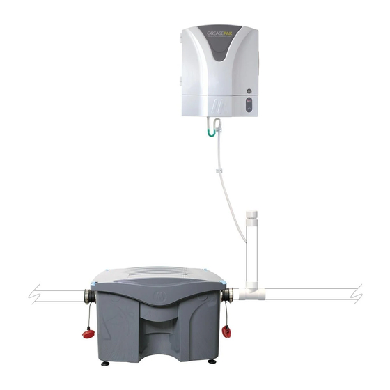
The Mechline BioCeptor is a combined system designed to retain and break down Fats, Oils and Grease (FOGs) to prevent them
from entering the drainage system.
The BioCeptor FOG Intercept and Treatment (F.I.T) unit works in conjunction with the GreasePak bio-fluid dosing module, which
doses highly effective microorganisms into the F.I.T unit once a day. The GreasePak bio-fluid formula breaks down the FOGs into
irreversible compounds that can easily pass through drainage and, most importantly, do not reform down the line (more on how
the bio-fluid works in Section 6.2.3).
The F.I.T unit will need to be maintained and cleaned professionally periodically, so that any organic loads can be removed, but
the frequency of servicing is greatly reduced as long as the dosing module is properly and correctly maintained. It is also highly
recommended that a food waste strainer is installed upsteam of the BioCeptor to minimise the amount of food waste particles
entering the F.I.T unit.
The GreasePak bio-fluid dosing module is the only product of its kind in the UK to be approved by the
British Board of Agrément (BBA) as a recognised form of effective grease removal.
The F.I.T unit has been independently tested and certified to ASME A112.14.3 and PDI G-101.
installation and operator manual
.............................................
..................................................................
...............................................................
...........................
..................................................
....................................
.................................................................
.............................................
...........................
LEAVE THIS MANUAL WITH THE OPERATOR AFTER INSTALLATION
Page
1
2
3
GreasePak
bio-fluid
4
dosing module
6
10
15
18
19
19
FOG Intercept
and Treatment
(F.I.T) unit
REVISION: 04/2019 | page 1 of 20
Advertisement
Table of Contents

Related Manuals for MECHLINE GreasePak


Summarization of Contents
Chapter 2. RATINGS and SPECIFICATIONS
2.1 BATTERY SPECIFICATIONS
Details about the GreasePak Dosing Module battery.
2.2 ELECTRICAL SPECIFICATIONS
Electrical requirements for the BioCeptor system.
2.3 DIMENSIONS & WEIGHTS
Physical dimensions and weight of the units.
2.4 PRODUCT CONFORMITY
Compliance with directives and standards.
Chapter 3. PRODUCT SAFETY
3.1 IDENTIFICATION AND COMPANY
Product identifier, uses, and distributor details.
3.2 HAZARDS AND FIRST AID
Hazard identification, classification, and first aid measures.
3.3 HANDLING, STORAGE & EXPOSURE CONTROLS
Safe handling, storage, and personal protection.
3.4 FIRE, RELEASE, AND DISPOSAL
Firefighting, accidental release, and disposal procedures.
3.5 PROPERTIES AND COMPLIANCE
Physical/chemical properties, stability, and regulations.
Chapter 4. LOCATION ADVICE
4.1 F.I.T Unit Installation Location
Guidance on installing the F.I.T unit internally on a level surface.
4.2 F.I.T Unit Levelling Feet
Information on adjustable levelling feet for the F.I.T unit.
4.3 GreasePak Dosing Module Placement
Advice on siting the GreasePak dosing module.
Continuing Chapter 4. LOCATION ADVICE
4.6 Dosing Module Mounting and Placement
Mounting height and placement advice for the module.
4.8 Delivery Tube Support and Routing
Proper support and routing for the delivery tube.
4.10 Site Considerations and Appliance Trapping
Advice for high FOG sites and appliance trapping.
Chapter 5. INSTALLATION INSTRUCTIONS
5.1 INSTALLATION REQUIREMENTS
General requirements before installation.
5.2 INSTALLATION STEPS
Step-by-step guide for installing the BioCeptor system.
Continuing Chapter 5. INSTALLATION INSTRUCTIONS
5.2.5 RUBBER CONNECTORS AND PLUGS
Using rubber connectors and plugs for pipework.
5.2.7 AIR ADMITTANCE VALVE AND DRAIN TEE
Installing the air admittance valve and drain tee fitting.
5.2.8 FLUID ENTRY HOLE AND ELBOW FITTING
Drilling fluid entry hole and fitting the blue elbow.
5.2.10 BALL VALVE AND STRAINER RECOMMENDATION
Recommending ball valve and strainer installation.
Continuing Chapter 5. INSTALLATION INSTRUCTIONS
5.2.12 DOSING MODULE FIXING
Fixing the GreasePak dosing module to the wall.
5.2.15 DELIVERY TUBE LENGTH DETERMINATION
Determining and cutting the delivery tube length.
5.2.16 DELIVERY TUBE FITTING
Fitting the delivery tube to the module and upstand.
5.2.18 SECURING DELIVERY TUBE
Using clips to secure the fluid delivery tube.
Continuing Chapter 5. INSTALLATION INSTRUCTIONS
5.2.20 BIO-FLUID BOX INSTALLATION
Hanging the bio-fluid box in the dispenser.
5.2.22 DOSING MODULE COVER REMOVAL
Removing the front cover of the dosing module.
5.2.23 FIRST FLUID BOX PRIMING
Priming the system with the first fluid box.
5.2.25/5.2.26 DELIVERY SETTINGS AND ADJUSTMENTS
Understanding and adjusting delivery time, volume, and clock.
Chapter 6. OPERATING INSTRUCTIONS
6.1 GENERAL ADVICE
General guidelines for operators.
6.2.1-6.2.3 SYSTEM FUNCTION AND BIO-FLUID INFO
How the BioCeptor works and bio-fluid safety/function.
6.2.5-6.2.10 BIO-FLUID MANAGEMENT AND MAINTENANCE
F.I.T unit emptying, bio-fluid replacement, storage, and duration.
6.2.11 BIO-FLUID LEAKS AND SPILLS
Procedures for bio-fluid leaks or contact.
Continuing Chapter 6. OPERATING INSTRUCTIONS
6.2.12-6.2.14 DOSING MODULE AND BATTERY CHECK
Changing dosing module time, fluid level, and battery life.
6.2.15 REMOTE SEWAGE SYSTEMS
Using BioCeptor with remote aerobic/anaerobic systems.
6.3 BIOCEPTOR F.I.T UNIT SERVICING AND CLEANING
Advice on periodic maintenance and cleaning by contractors.
Continuing Chapter 6. OPERATING INSTRUCTIONS
6.4 BIOCEPTOR F.I.T UNIT CLEANOUT LOCATIONS
Step-by-step guide for cleaning and maintaining the F.I.T unit.
Waste Disposal and Record Keeping
Requirements for waste disposal and record keeping.
Continuing Chapter 6. OPERATING INSTRUCTIONS
6.5 BIOCEPTOR F.I.T UNIT TROUBLE SHOOTING
Troubleshooting common issues like slow drainage and leaks.
6.6 BIOCEPTOR F.I.T UNIT PARTS DIAGRAM
Exploded diagram of F.I.T unit components.
Chapter 7. BIOCEPTOR F.I.T UNIT SIZING GUIDE
BioCeptor Flow Rates
Table of flow rates based on ASME standards.
Sizing Rationale and Recommendations
Explanation of sizing criteria and FOG capture.
7.1 POT WASH SINKS AND PRE-RINSE TABLING
Protecting drainage from pot wash sinks and pre-rinse bowls.
Continuing Chapter 7. BIOCEPTOR F.I.T UNIT SIZING GUIDE
7.2 FOOD WASTE DISPOSERS
Advice against connecting food waste disposers.
7.3 OTHER APPLIANCES
Connecting appliances like combi ovens and dishwashers.
7.4 LOW and HIGH FOG PRODUCING SITES
Guide to determining site FOG production levels.
Continuing Chapter 7. BIOCEPTOR F.I.T UNIT SIZING GUIDE
7.5 EXAMPLES
Examples of site FOG production scoring.
7.6 FIGURE 1 INSTALLATION EXAMPLE
Example of BioCeptor installation for low FOG sites.
7.7 FIGURE 2 INSTALLATION EXAMPLE
Example of BioCeptor installation for high FOG sites.
Chapter 8. BBA APPROVED
GreasePak Biological Grease Degradation System Summary
Summary of the BBA Agrément Certificate for the system.
Agrément Certification Key Factors Assessed
Key factors assessed for BBA approval.
Chapter 9. ON-GOING REQUIREMENTS
9.1 MAINTENANCE
Requirements for ongoing maintenance and cleaning.
9.2 GENERAL CLEANING
General cleaning advice for the BioCeptor system.
9.3 OPERATIONAL TIPS
Fundamental tasks for staff to perform regularly.
Chapter 10. AFTER SALES and SERVICE SUPPORT
10.1 TECHNICAL ASSISTANCE
Contact information for technical support.
10.2 WARRANTY
Details on the product warranty and exclusions.
10.3 SPARE PARTS
Information on how to obtain spare parts.
Need help?
Do you have a question about the GreasePak and is the answer not in the manual?
Questions and answers