Table of Contents
Advertisement
Advertisement
Table of Contents

Related Manuals for SonicWALL SWS14 Series


Summary of Contents for SonicWALL SWS14 Series
- Page 1 ® SonicWall Switch Getting Started Guide...
-
Page 2: Table Of Contents
Modifying the MAC Address Table ............51 SonicWall Switch Getting Started Guide... - Page 3 Configuring a Dedicated Link for SonicWall Access Points ....... . .
-
Page 4: Registering Your Switch
Registering Your Switch SonicWall Switches should be registered on MySonicWall prior to using them. Select the support license for either 1 year or 3 year support, including firmware updates. To register your Switch on MySonicWall: 1 Find the product label on the bottom surface of your Switch enclosure and make a note of the serial number and authentication code. -
Page 5: Overview
IEEE 802.3at/af ports, PoE port management, voice VLAN, QoS, static routing, 802.1x authentication, and access point management. The main applications envisioned for SonicWall Switches is in branch office scenarios where they are managed by firewalls. Application scenarios where the Switches are managed directly through their local UI are seen as less prevalent. -
Page 6: Branch Office
SD-WAN plays a major role in a branch solution by providing an essential software component. Daisy Chaining of Switches allows up to Four Switches to be concurrently managed by the firewall. Three can be daisy chained with one parent Switch, or two parent Switches sharing one child Switch. SonicWall Switch Getting Started Guide Overview... -
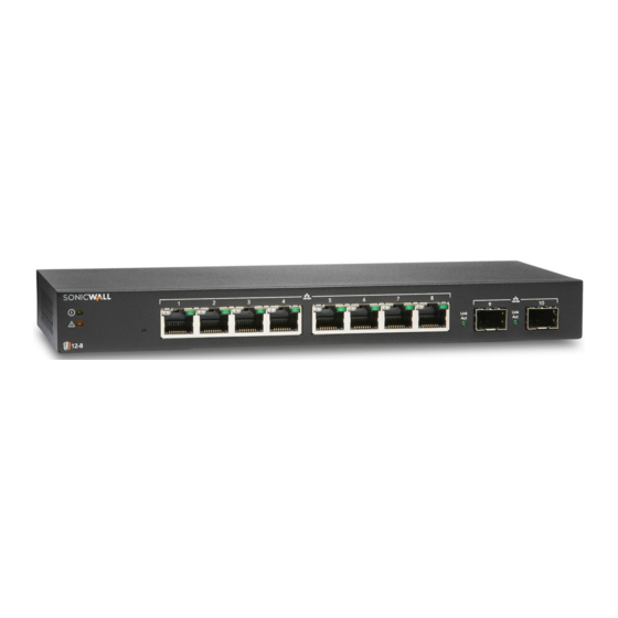
Page 7: Hardware Overview
The SWS12-8POE supports Power Over Ethernet (PoE) conforming to 802.3a/f as Power Sourcing Equipment (PSE). These Switches can be managed from a SonicWall firewall, WiFi Cloud Manager, or directly from on-premises or cloud based systems. From top to bottom, the models are: •... - Page 8 Reset button: Press to reset the Switch to current Optional connector allows connection to ground settings. Press for 10 seconds to enter Recovery Mode. Note: Returns Switch to default configuration. RJ45 LAN Ports: 10/100/1000 Mbps RJ45 LAN ports SonicWall Switch Getting Started Guide Overview...
-
Page 9: Sws12-10Fpoe, 14-24Fpoe, 14-24, 14-48Fpoe, 14-48
添付の電源 コ ー ド に関 し て 電気安全を確保する ために、 弊社製品にご使用いただ く 電源 コ ー ド は必ず 製品同梱の電源 コ ー ド を ご使用 く だ さ い。 こ の電源コ ー ド は他の製品では使用で き ません。 SonicWall Switch Getting Started Guide Overview... - Page 10 SFP Speed (per SFP port): Off = No traffic; Green = 1 Lit = PoE mode on Gbps LAN/PoE Mode Selector: Press to change between SFP Ports: 1 Gbps ports LAN and PoE LED display modes. Refer to feature 9. AC Power Port SonicWall Switch Getting Started Guide Overview...
- Page 11 Press to change between SFP+ Link/Act LED (per SFP+ port): Off = No link; LAN and PoE LED display modes. Refer to feature 10. Green = active link; Blinking = packet transfer in process AC Power Port SonicWall Switch Getting Started Guide Overview...
- Page 12 Press to change between SFP+ Link/Act LED (per SFP+ port): Off = No link; LAN and PoE LED display modes. See feature 10. Green = active link; Blinking = packet transfer in process AC Power Port SonicWall Switch Getting Started Guide Overview...
-
Page 13: About Poe
40. About SFP/SFP+ Overview The SFP interfaces on SWS12 series Switches support only 1 Giga-bit per second (Gb/s). The SFP+ interfaces on SWS14 series Switches support only 10 and 1 Gb/s. NOTE: Auto-Negotiation for SFP/SFP+ ports is not currently supported. On the SWS14 Series, SFP+ ports can be manually set to 1 and 10 Gbps. - Page 14 0 — 40 (non-condensing) Humidity 5 — 95% 5 — 95% 5 — 95% 5 — 95% 5 — 95% 1.Contact your SonicWall sales representative for information on available SonicWall SFP/SFP+ modules and ca- bles: https://www.sonicwall.com/customers/contact-sales/ SonicWall Switch Getting Started Guide Overview...
-
Page 15: Connecting To The Switch
4 The Switch management console login screen now appears. To login to the management console: 1 Enter username as admin and password as password to start a management console session for the first time. SonicWall Switch Getting Started Guide Connecting to the Switch... - Page 16 3 Click OK and then connect the Switch to your DHCP-enabled network. 4 On the DHCP server, find and write down the IP address allocated to the device. Use this IP address to access the management interface. SonicWall Switch Getting Started Guide Connecting to the Switch...
-
Page 17: Connecting Via The Console Port
1 Locate the DB-9 to RJ45, serial cable that was shipped with the Switch and connect it from a PC to the leftmost port labeled console on the Switch. 2 For instructions on connection through the console port see: • https://www.sonicwall.com/support/knowledge-base/how-can-i-login-to-the-appliance-using-the-c ommand-line-interface-cli/170505641032025/ SonicWall Switch Getting Started Guide Connecting to the Switch... -
Page 18: Upgrading The Firmware
Downloading and re-booting of the Switch may take over ten minutes. Wait for the front panel LEDs to flash, indicating the Switch has rebooted. Via the Local UI This procedure supports all SonicWall Switch models. The network setup for the upgrade is summarized in the following diagram. SonicWall Switch Getting Started Guide... - Page 19 5 to 10 minutes. At completion, the Switch LEDs will flash indicating a reboot. 3 Once the Switch has rebooted, log back into the Switch and verify the firmware version is properly updated. SonicWall Switch Getting Started Guide Upgrading the Firmware...
-
Page 20: Via Tftp
1 If you do not have a TFTP server on your PC, download one. Below, we show one from: https://tftpd32.jounin.net/ 2 Download the new firmware from software.sonicwall.com. 3 Bring up the TFTP server, note IP address and browse to the downloaded firmware. - Page 21 ...[TFTP sever addrese/file name]...flash:normal image [1 or 2] 2 The flash process may take over 5 minutes. Once it completes, enter reboot to reboot the Switch with the new firmware revision. SonicWall Switch Getting Started Guide Upgrading the Firmware...
-
Page 22: Configuring From The Firewall
Configuring from the Firewall Firewall Switch Controller UI Starting with release 6.5.4.6, SonicOS supports firewall management of SonicWall Switches. The Switch Controller user interface consists of pages and sub-pages. • Overview • Pre-Plan — Before Adding a Switch on page •... -
Page 23: Before Adding A Switch
Make any other connections from the firewall to the Switch when you add the Switch. • Make any changes in the Reserved VLAN range for the firewall interface before adding the SonicWall Switch. If the Reserved VLAN range changes after connecting the Switch, then the Switch must be removed and re-added. -
Page 24: Adding A Switch To A Firewall With Zero-Touch
SonicOS 6.5.4.6 or higher. The Switch should be at 1.0.0.0-19 or higher. The firewall must be setup to add Switches with Zero Touch. To prepare firewall: 1 Check that the firewall firmware is at the most recent level. SonicWall Switch Getting Started Guide Configuring from the Firewall... - Page 25 2 Select an interface on the firewall to connect to the Switch. Navigate to Manage > Network > Interfaces and select an interface, then click on Configure and select the Advanced tab. Select Enable AutoDiscovery of SonicWall Switches: 3 Connect the Switch to the selected firewall interface.
- Page 26 5 Navigate to Manage > Switch Controller > Overview, Click on Authorize button to add the Switch to firewall: 6 The network topology will now appear on the Overview. SonicWall Switch Getting Started Guide Configuring from the Firewall...
-
Page 27: Adding A Switch To A Firewall Manually
Switch Local UI, or the Command Line Interface accessible through the console port. NOTE: To change the Reserved VLAN range on the firewall, do so before adding the SonicWall Switch. If the Reserved VLAN range changes after connecting the Switch, then the Switch must be removed and re-added. - Page 28 4 Once the dialog boxes are complete, click on Add. 5 Go to the Overview, the new Switch will appear graphically with the ports linking the Switch and the firewall indicated. SonicWall Switch Getting Started Guide Configuring from the Firewall...
-
Page 29: Changing The Switch Configuration
Click the “three-dot” box to the right of the switch graphic in the Physical Overview display and then select Edit. Check the Status and Link Details Navigate to Switch Controller > Overview and hover over the Switch port. SonicWall Switch Getting Started Guide Configuring from the Firewall... -
Page 30: Enabling The Switch
To remove a Switch from a firewall, navigate to Switch Controller > Overview > Physical View and click on the Delete Switch. This can also be done by going to Switch Controller > Switches and clicking on Configure. See Changing the Switch Configuration on page 29. SonicWall Switch Getting Started Guide Configuring from the Firewall... -
Page 31: Restarting The Switch
1 Click on the 3 dot menu on the Switch image on the Overview page and click on Reboot Switch. To reboot the Switch to factory defaults: 1 Use a paper clip to depress the front panel reset Switch for over 10 seconds. Reset Switch SonicWall Switch Getting Started Guide Configuring from the Firewall... -
Page 32: Adding A Vlan
VLAN group. IMPORTANT: To change the Reserved VLAN range on the firewall, do so before adding the SonicWall Switch. If the Reserved VLAN range changes after connecting the Switch, then the Switch must be removed and re-added. - Page 33 For more on CoS definition, see Setting Up QoS on page 38. NOTE: The Switch remarks incoming voice VLAN traffic tags for voice priority and DSCP as defined by these settings. SonicWall Switch Getting Started Guide Configuring from the Firewall...
- Page 34 To Enable/Disable Voice VLAN from the Physical View: Simply go to MANAGE > Switch Controller > Overview and click on the port. When the sideband display appears scroll to Voice VLAN state as shown below. SonicWall Switch Getting Started Guide Configuring from the Firewall...
-
Page 35: Adding Static Routes
2 Fill out the dialog box. Destination IP address with ‘0’ as the last octet: x.x.x.0. Subnet Mask for the destination. Gateway: IP address gateway between Switch and destination. 3 Click on OK. SonicWall Switch Getting Started Guide Configuring from the Firewall... -
Page 36: Editing Dns
Editing DNS To set DNS addresses go to Switch Controller > Switches and select Network, then click on Edit DNS. SonicWall Switch Getting Started Guide Configuring from the Firewall... -
Page 37: Setting Up The Ports
2 When the list appears click on the edit button for the specific port. 3 The port setup dialog for the specific port will now appear to the right of the screen. SonicWall Switch Getting Started Guide Configuring from the Firewall... -
Page 38: Setting Up Qos
Robin (WRR). The classification of packets can be set as 802.1p or DSCP (Differentiated Sevices Code Point), or as both. 3 Select the IPDSCP screen to set DSCP codes to specific Queues. SonicWall Switch Getting Started Guide Configuring from the Firewall... - Page 39 In the CoS (Class of Service) screen, the CoS priority tag values, where 0 is the lowest and 7 is the highest are related to eight traffic priority queues from 1 to 8, where one is the lowest priority and eight is the highest priority. SonicWall Switch Getting Started Guide Configuring from the Firewall...
-
Page 40: Setting Up Poe
• User Defined - Sets the maximum amount of power that can be delivered by a port. NOTE: The User Power Limit can only be implemented when the Auto Class value is set to User-Defined. SonicWall Switch Getting Started Guide Configuring from the Firewall... -
Page 41: Setting Up Users
Setting Up Users Users with different access levels, admin and user, can be defined by navigating to Switch Controller > Switches and clicking on Users. Users are limited to Non-Configuration Mode. SonicWall Switch Getting Started Guide Configuring from the Firewall... -
Page 42: Setting Up 802.1X Authentication
1 In MANAGE > Switch Controller > Switches click on Radius Server. When the server list appears click on Add Radius Server. 2 To enable the Radius server, set the Authorized Port as 1812. SonicWall Switch Getting Started Guide Configuring from the Firewall... -
Page 43: Daisy-Chaining Switches
1 Select a Switch in standalone configuration to daisy-chain the additional Switch to. Then determine which ports to use to connect the additional Switch. 2 Go to MANAGE | Switch Controller > Overview and click on Add Switch. SonicWall Switch Getting Started Guide Configuring from the Firewall... - Page 44 Switch as Daisy-chain. 5 Navigate to Switch Controller > Overview and click on Physical View. The new Switch will appear graphically with the ports linking the Switch and the firewall indicated. SonicWall Switch Getting Started Guide Configuring from the Firewall...
-
Page 45: Connecting Access Points
5 In the firewall GUI, navigate to Switch Controller > Overview, click List View. Click on the pencil icon to configure port 3. To create a dedicated uplink, set the Portshield Interface to X4, and move the Dedicated Uplink Switch to the right. SonicWall Switch Getting Started Guide Configuring from the Firewall... - Page 46 1 Login to the firewall as an adminstrator and go to MANAGE | Network > Interfaces page and click on the configure icon for the inteface the Switch is supported on. 2 Select WLAN for the Zone type. 3 Select the Static IP Mode for the Mode/IP Assignment. SonicWall Switch Getting Started Guide Configuring from the Firewall...
- Page 47 To Configure the WLAN Zone: 1 In the MANAGE view on the System Setup | Network > Zones page, click the Edit icon in the Configure column of the WLAN row. SonicWall Switch Getting Started Guide Configuring from the Firewall...
- Page 48 3 Select the checkboxes to enable security services on this zone. Minimally, you would select Enable Gateway Anti-Virus Service, Enable IPS, and Enable Anti-Spyware Service, if your wireless clients are all running Spyware Service. If your wireless clients are all running SonicWall Client Anti-Virus, select Enable Client .
- Page 49 WPA2 as the authentication type if all client devices support it. TIP: PSK uses a personal passphrase for authentication, EAP uses an Enterprise RADIUS server. 5 Select the Cipher Type. When using WPA and WPA2, SonicWall recommends AES for maximum security. NOTE: Older client devices might not support AES.
- Page 50 2 From the drop-down menu, select the schedule for when the SonicWave operates as a WIDP sensor or select Create new schedule... to specify a different time; default is Always on. SonicWall Switch Getting Started Guide Configuring from the Firewall...
-
Page 51: Modifying The Mac Address Table
The dynamic MAC address table lists currently learned MAC addresses and accompanying Port and VLAN IDs. The defined MAC Aging time deterimines how current this information is. This table provides details on the LAN supported by the Switch. SonicWall Switch Getting Started Guide Configuring from the Firewall... -
Page 52: Checking Port Statistics
Checking Port Statistics The statistics table for a Switch can also be reached through Switch Controller > Switches > Statistics. This table presents details on port-by-port performance. SonicWall Switch Getting Started Guide Configuring from the Firewall... -
Page 53: Setting Spanning Tree Protocol
• STP Mode — Sets the protocol version to Multiple (MSTP) or Rapid (RSTP). • STP State — Enables or Disables spanning tree operation on the Switch. 3 Click on OK. SonicWall Switch Getting Started Guide Configuring from the Firewall... -
Page 54: Changing Firmware
Simply go to MANAGE | Switch Controller > Overview and click on the port. When the sideband display appears scroll to STP state as shown below. Changing Firmware Switches > Firmware enables uploading of new firmware and changing of partitions or firmware slots to boot from. SonicWall Switch Getting Started Guide Configuring from the Firewall... -
Page 55: Configuring From Local Ui
To access the Switch local user interface, refer to Connecting over Ethernet on page 15. For a detailed description of the the Switch Local User Interface, see Switch documentaion on the SonicWall documentaition portal — https://www.sonicwall.com/support/technical-documentation/?language=English SonicWall Switch Getting Started Guide... -
Page 56: Configuring Basic Topologies
• Configuring VLAN(s) With Dedicated Uplink(s) on page • Configuring a Dedicated Link for SonicWall Access Points on page About Topologies Basic topologies for an SWS12- or SWS14-series Switch include: • Common uplink configuration • Dedicated uplink configuration •... -
Page 57: Connecting The Switch Management Port To A Firewall
All port-based configuration operations are disabled on the Switch port designated as the Switch management and Switch uplink ports. This action ensures that configuration operations on these critical ports do not lead to Switch-reachability issues jeopardizing the integration solution. SonicWall Switch Getting Started Guide Configuring Basic Topologies... -
Page 58: Configuring A Common Uplink
Configuring a Common Uplink SonicWall Switches can be managed by the firewall, thereby providing a unified management option. The common uplink configuration allows a single link between the firewall and the Switch to be designated as the uplink that carries all PortShield traffic, both management and data. Both the firewall and Switch ports are configured as trunk ports for carrying tagged traffic for VLANs corresponding to all the firewall interfaces. - Page 59 The Add Switch button will appear in Physical View, List View, and VLAN View. a Click on Add Switch. b When the dialog box appears, set the Switch Uplink and Switch Management ports to 2 and the Firewall Uplink to X3. SonicWall Switch Getting Started Guide Configuring Basic Topologies...
- Page 60 3 In Overview > Physical View, a single link should now appear between the firewall and the Switch. SonicWall Switch Getting Started Guide Configuring Basic Topologies...
-
Page 61: Configuring A Dedicated Uplink
• The uplink between X3 on the firewall and port 1 on the SonicWall Switch is used to manage the Switch. In this configuration, X3 is configured in the same subnet as the IP of the Switch. - Page 62 4 Once the the Switch port is enabled, go to Switch Port Settings as shown below. Set portshields to support dedicated uplinks. In the dialog below, port 7 is portshielded to X5. Click OK. SonicWall Switch Getting Started Guide Configuring Basic Topologies...
-
Page 63: Configuring A Hybrid System With Common And Dedicated Uplink(S)
Hybrid Link Topology shows a hybrid uplink integration topology of a SonicWall firewall with a SonicWall Switch: • The dedicated uplink between X0 on the firewall and port 11 on the Switch is set up to carry PortShield traffic for X0. -
Page 64: Configuring Isolated Links For Management And Data Uplinks
Switch: • The link between X2 on the firewall and port 1 on the Switch carries management traffic to the Switch. In such a configuration, X2 is configured in the same subnet as the IP of the SonicWall Switch. NOTE: When the Switch is configured with Isolated uplink the switch IP should be configured at a Static IP address. - Page 65 4 When a dialog box appears, enter the data requested and the following settings: • Switch Management = 1 • Firewall Uplink = X3 • Switch Uplink = 2 5 When complete with configuration click on ADD. SonicWall Switch Getting Started Guide Configuring Basic Topologies...
-
Page 66: Configuring Ha And Portshields With Dedicated Uplink(S)
X0 on the secondary and port 1 of the Switch. In such a configuration, when the Switch is provisioned, the Primary Switch Management and Secondary Switch Management are set to 1. SonicWall Switch Getting Started Guide Configuring Basic Topologies... - Page 67 The Firewall Uplink and Switch Uplink options are set the same in this configuration to support the redundant firewalls. b Set management uplinks for both Primary and Secondary firewalls to to Switch port 1 and firewall interface X0. SonicWall Switch Getting Started Guide Configuring Basic Topologies...
-
Page 68: Configuring Ha Using Two Switch Management Ports
Add Switches manually after creating the HA pair. Activating HA mode after Switches are added will not work. 1 Add the Switch and set up the data uplink. 2 Configure the options: SonicWall Switch Getting Started Guide Configuring Basic Topologies... - Page 69 HA mode. The primary Firewall Uplink option and both the primary and secondary Switch Uplink options are set to None. b Set Firewall and Switch Uplink options to None. 3 Click ADD. SonicWall Switch Getting Started Guide Configuring Basic Topologies...
-
Page 70: Configuring Ha And Portshield With A Common Uplink
Switch 1 is set up as a common uplink. Similarly, the link between X2 and Switch 2 is set up as a common uplink. The PortShield hosts X0 are connected to a different Switch (which could be a SonicWall Switch or any other vendor’s Switch) to avoid looping of packets. - Page 71 Switch uplink for the primary firewall Switch uplink for the secondary firewall Switch 2 Interfaces: Host-facing interface portshielded to X0 Switch uplink for the primary firewall Switch uplink for the secondary firewall SonicWall Switch Getting Started Guide Configuring Basic Topologies...
-
Page 72: Configuring Vlan(S) With Dedicated Uplink(S)
IMPORTANT: To change the Reserved VLAN range on the firewall, do so before adding the SonicWall Switch. If the Reserved VLAN range changes after connecting the Switch, then the Switch must be removed and re-added. Configuring a Dedicated Uplink for VLANs Topics: •... - Page 73 • Common uplink option if support is needed for an common trunk interface to carry PortShield traffic for other firewall interfaces along with VLAN(s) support. 2 Configure the dedicated link by: a Choosing a Switch port that is connected physically to the firewall interface. SonicWall Switch Getting Started Guide Configuring Basic Topologies...
- Page 74 VLAN 150, and Port 12 is an access port carrying untagged traffic for VLAN 200. Ports 10, 11, and 12 are portshielded to X5 through the dedicated link between X5 and port 2. SonicWall Switch Getting Started Guide Configuring Basic Topologies...
-
Page 75: Configuring A Dedicated Link For Sonicwall Access Points
RJ45 are portshielded to that dedicated port. If the SonicWall access points are behind the firewall and are to be managed, the pair of ports on the firewall and the Switch must be configured as a dedicated link. The dedicated port on the firewall must be configured as WLAN. -
Page 76: Sonicwall Support
SonicWall Support Technical support is available to customers who have purchased SonicWall products with a valid maintenance contract. The Support Portal provides self-help tools you can use to solve problems quickly and independently, 24 hours a day, 365 days a year. To access the Support Portal, go to https://www.sonicwall.com/support. -
Page 77: About This Document
The information in this document is provided in connection with SonicWall Inc. and/or its affiliates’ products. No license, express or implied, by estoppel or otherwise, to any intellectual property right is granted by this document or in connection with the sale of SonicWall products.
Need help?
Do you have a question about the SWS14 Series and is the answer not in the manual?
Questions and answers