Table of Contents
Advertisement
Quick Links
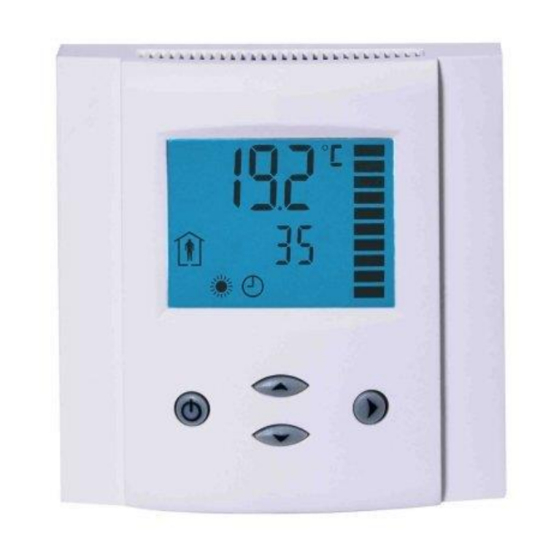
Programmable operation terminal for MODBUS
OPA2-MOD
Application
The operation terminal controls typically a single room control unit. The device measures room temperature and humidity
(for –H type) through integrated sensors. Two additional digital inputs may be configured for window contact, key
switches or motion detectors. The operation mode may then be controlled based on these inputs. An external temperature
may be measured through the additional temperature input. This may be useful for underfloor heating, sensor averaging
for large rooms, outdoor temperatures etc.
The operation terminal communicates through a galvanically isolated RS485 interface via the MODBUS protocol in slave
mode.
Ordering
Model
Item#
OPA2-MOD
40-50 0014
OPA2-MOD-H
40-50 0053
Supported Modbus commands:
-
03 (0x03): Read multiple registers
-
06 (0x06): Write single register
-
16 (0x10): Write multiple registers
Commands 03 and 16 can handle up to 32 registers. The Modbus slave transmits the values as signed 16 bit integers with
one digit below the decimal point. This results in the following range: -9999.9 to 9999.9
In an event of an out-of-range command addressing or an unsupported command, the Modbus slave responds with an
exception message according to the Modbus specification.
Dimensions [mm](in)
Doc: 70-00-0290, V1.0 R0, Date: 20160208
Subject to alteration
Features
Display
RT
yes
1
yes
1
88 (3.5)
LCD display with backlight four keys
Internal temperature sensor
With –H model, internal humidity sensor
1 external temperature input
2 digital inputs, which can be configured for window/door contacts
or motion detectors.
Up to 5 zones may be handled by one operation terminal
Detailed configuration possible
RS485 2-wire MODBUS standard in accordance to EIA/TIA 485
Slave type of communication
Galvanic isolated bus connection
Flush mounted on standard EU/UK/CH installation box
DI
rH
Modbus communication module with one internal
2
-
temperature sensor and one external temperature
input plus two binary inputs.
As above with internal humidity sensor 3%
2
1
accuracy.
32
21
(1.2)
(0.8)
© Vector Controls GmbH, Switzerland
OPA2-MOD(-H)
Description
Page 1
Advertisement
Table of Contents

Related Manuals for Vector 40-50 0014


Summarization of Contents
Features
Internal Temperature Sensor
Measures room temperature using an integrated sensor.
Internal Humidity Sensor
Measures internal humidity for the -H model.
External Temperature Input
Connects an external temperature sensor for additional readings.
Digital Inputs
Two inputs for window contacts or motion detectors.
Modbus Communication
RS485 2-wire MODBUS standard, slave type.
Application
Room Control Unit Functionality
Controls single room units, measuring temp/humidity, uses digital inputs.
External Sensor Usage
For underfloor heating, averaging, or outdoor temperatures.
RS485 Interface
Galvanically isolated RS485 interface using MODBUS protocol.
Ordering Information
OPA2-MOD
Modbus module with internal/external temp sensors and two binary inputs.
OPA2-MOD-H
Includes internal humidity sensor in addition to OPA2-MOD features.
Supported Modbus Commands
Register Operations
Commands 03, 06, 16 for reading/writing multiple or single registers.
Data Format and Range
Transmits signed 16-bit integers, range -9999.9 to 9999.9.
Technical Data: Power Supply
Power Requirements
Specifies voltage, frequency, and VA rating.
Terminal Connectors
Wire gauge compatibility for terminal connections.
Technical Data: Sensors
Internal Temperature Sensor
Range and accuracy for the integrated temperature sensor.
Humidity Sensor AES-HT-Ax
Range, accuracy, and tolerance for the humidity sensor.
Technical Data: Signal Inputs
Temperature Input(RT)
Range and accuracy for the external temperature input.
Digital Inputs
Defines input range and type (potential free).
Technical Data: Network
Hardware Interface
RS485 interface, nodes per network/segment, conductors.
Topology & Termination
Network topology, max length, line termination.
Technical Data: Environment
Operation Conditions
Climatic and temperature conditions during operation.
Transport & Storage Conditions
Climatic and temperature conditions for transport/storage.
Technical Data: Standards & General
EU Standards Compliance
EMC, Low Voltage Directives, and product standards.
Material and Dimensions
Material of casing, mounting plate, and device dimensions.
Security Advise
Device Intended Use
For comfort applications; owner responsibility for safety.
Failure Consequences
Failure to follow specs endangers life, voids warranty.
Connection Diagram and Terminal Description
Connection Diagram Notes
GND vs Modbus common, line polarization, termination resistor.
Terminal Pinout
Detailed description of each terminal's function and signal.
Mounting Location and Installation
Optimal Mounting Location
Recommended interior wall placement, avoiding heat sources.
Installation Procedure
Step-by-step guide for mounting and connecting the device.
Display and Operation Overview
Display Elements
Explains large digits, small digits, vertical bar, and zone indication.
User Interface Buttons
Describes the function of POWER, UP, DOWN, and OPTION buttons.
Operation Modes and Symbols
Supported Operation Modes
Lists modes like Comfort, Standby, Energy Hold Off.
Control Symbols
Explains symbols for Heating, Cooling, Fan, etc.
Idle Mode and Error Messages
Idle Mode Display
How the display behaves when idle and how to configure it.
Error Message Handling
Describes Err1 (communication timeout) and Err2 (sensor issues).
Accessing Configuration Parameters
Parameter Entry Procedure
Step-by-step guide to access and change parameters via buttons.
Setup Parameters List
Communication Settings (CP00-CP04)
Parameters for Modbus address, baud rate, parity, and broadcast.
Zone and Display Settings (CP05-CP13)
Parameters for number of zones, setpoint change, clock format, temperature unit.
Sensor and Timeout Settings (CP14-CP20)
Parameters for fan speeds, sensor calibration, and communication timeouts.
Register Definitions: Terminal Setup
Hardware and Software Info Registers
Registers for hardware/software version and revision.
Communication Configuration Registers
Registers for Modbus address, baud rate, parity, and mode.
Operation and Timing Registers
Registers for idle mode timeout, sensor calibration, and communication timeouts.
Register Definitions: Operation State, Symbols & Alarms
Operation State Registers
Registers for ON/OFF state and occupied/unoccupied status.
Symbol Display Registers
Registers to control the display of fan, alarm, heating, cooling, and mode symbols.
Alarm Text Registers
Registers for displaying custom alarm text strings and their location.
Display Configuration: OFF Mode
Large Digits Content
Selects what is displayed in the large digits in OFF mode.
Small Digits Content
Selects what is displayed in the small digits in OFF mode.
Vertical Bar Content
Selects the data shown on the vertical bar in OFF mode.
OFF Mode Symbols
Configures which symbols are displayed when the unit is in OFF mode.
Display Configuration: Idle Mode
Idle Mode Large Digits
Configures content for large digits during idle mode.
Idle Mode Small Digits
Configures content for small digits during idle mode.
Idle Mode Vertical Bar
Configures content for the vertical bar during idle mode.
Idle Mode ON Letters
Defines text strings displayed in ON mode when idle.
Display Configuration: Zone 1
Zone 1 Large Digits Content
Selects data for large digits in Zone 1 display.
Zone 1 Value Digits Unit
Specifies units for displayed values in Zone 1.
Zone 1 Small Digits Content
Selects data for small digits in Zone 1 display.
Zone 1 Setpoint Configuration
Configures comfort/standby setpoints, steps, and limits for Zone 1.
Input Configuration: Sensors
Internal Temperature Sensor Configuration
Enable/disable, calibration, and error state for internal temp sensor.
Internal Humidity Sensor Configuration
Enable/disable, calibration, and error state for internal humidity sensor.
External Temperature Input Configuration
Enable/disable, calibration, and error state for external temp input.
Input Configuration: Digital Inputs
Digital Input 1 Function Assignment
Assigns functions like remote disable or mode change to Digital Input 1.
Digital Input 2 Function Assignment
Assigns functions like remote disable or mode change to Digital Input 2.
Digital Input Behavior
Defines open/closed contact behavior for inputs and associated delays.
Fan String Configuration
Fan String Character Definition
Defines characters for up to four fan strings.
ASCII Character Mapping
Table mapping ASCII codes to displayable characters.
Need help?
Do you have a question about the 40-50 0014 and is the answer not in the manual?
Questions and answers