Sign In
Upload
Download
Table of Contents
Contents
Add to my manuals
Delete from my manuals
Share
URL of this page:
HTML Link:
Bookmark this page
Add
Manual will be automatically added to "My Manuals"
Print this page
×
Bookmark added
×
Added to my manuals
Manuals
Brands
AirSep Manuals
Oxygen Equipment
AS-B
Instruction manual
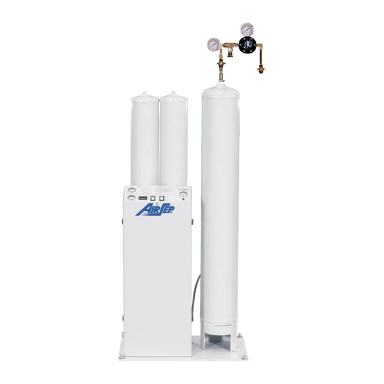
AirSep AS-B Instruction Manual
Psa oxygen generator
Hide thumbs
1
2
3
4
5
6
7
8
9
10
11
12
13
14
15
16
17
18
19
20
21
22
23
24
25
26
27
28
29
30
31
32
33
34
35
36
37
38
39
40
41
42
43
44
45
46
47
48
49
50
51
52
53
54
55
56
57
58
59
60
61
62
63
64
65
66
67
68
69
70
71
72
73
74
75
76
77
78
79
80
81
82
83
84
85
86
87
88
89
90
91
92
93
94
95
96
97
98
99
100
101
102
103
104
105
106
107
108
109
110
111
112
113
114
115
116
117
118
119
120
121
122
123
124
125
126
127
128
129
130
131
132
133
134
135
136
137
138
139
140
141
142
143
144
145
146
147
148
149
150
151
152
153
154
155
156
157
158
159
160
161
162
163
164
165
166
167
168
169
170
171
172
173
174
175
176
177
178
179
180
181
182
183
184
185
186
187
188
189
190
191
192
Table Of Contents
193
page
of
193
Go
/
193
Contents
Table of Contents
Troubleshooting
Bookmarks
Table of Contents
Airsep Representative
PSA Oxygen Generator
Table of Contents
List of Illustrations
1 Introduction
General
Warnings, Cautions, and Notes
References to Controls and Indicators with Tags or Labels
2 Safety
Potential Hazards
General
Safety Publications
3 System Description
General
4 Components Description
External Components
External Components — Front View
Figure 4.1: External Components - Front View
Adsorbers
Enclosure
Fuse Holder
Power Cord
Control Panel
Oxygen Outlet
Condensate Drain Outlet
On/Off Switch
Figure 4.2: Control Panel - AS-B and AS-D Models
Hour Meter (Not Available on AS-A Models)
Manifold Components
Manifold Components — AS-B Model
Figure 4.3: Manifold Components - AS-B Model
Manual Inlet Valve
Figure 4.4: Manifold Components - AS-L Model
Coalescing Filter
Feed Air Regulator
Filter Drain Valve
Particulate Filter (Not Available on AS-A Models)
Circuit Board/Plc
Pressure Switch
Relief Valves
Transformer
Accessory Kits
Air Hose
Regulator Kit/Assembly
Oxygen Hose
Magnalube-G
Additional Available Accessories
5 Installation
Handling and Unpacking
Pre-Installation Guidelines
Installation Instructions
Feed Air Connection Sizes and Hose Sizes
Figure 5.1: Typical Installation Arrangement
Oxygen Outlet Connection Sizes
6 Operation
Initial Start-Up
Shutdown
Normal Start-Up
Extended Shutdown
Start-Up after an Extended Shutdown
7 Maintenance
Daily Monitoring
Monthly Monitoring
Maintenance Chart
Removing the Front Cover of the Enclosure
Depressurizing the Filters
Figure 7.1: Interior View of AS-B Model
Changing Filter Elements
Depressurizing the Oxygen Generator
Adjusting the Feed Air Regulator
Adjusting the Pressure Switch
AS-A – AS-D Oxygen Generators
Signal Setting Chart
Figure 7.2: Pressure Switch for AS-A - AS-D
AS-D+ - AS-P Oxygen Generators
Technical Support
Troubleshooting Chart
Specifications
Figure A.1: Typical Pressure Profile and Valves Cycle Sequence
Figure A.2: Typical Installation Arrangement
Figure A.3: General Arrangement Drawing - AS-A
Flow Schematic – AS-A
Figure A.4: Flow Schematic - AS-A
Electrical Schematic – AS-A (120 V)
Figure A.5: Electrical Schematic - AS-A (120 V
Electrical Schematic – AS-A (240 V)
Figure A.6: Electrical Schematic - AS-A (240 V
Figure A.7: General Arrangement Drawing - AS-B
Figure A.8: General Arrangement Drawing - AS-D
Figure A.9: Flow Schematic - AS-B and AS-D
Electrical Schematic – AS-B and AS-D (120 V)
Figure A.10: Electrical Schematic - AS-B and AS-D (120 V
Electrical Schematic – AS-B and AS-D (240 V)
Figure A.11: Electrical Schematic - AS-B and AS-D (240 V
General Arrangement Drawing – AS-D+
Figure A.12: General Arrangement Drawing - AS-D
Flow Schematics – AS-D+
Figure A.13: Flow Schematics - AS-D
Figure A.14: General Arrangement Drawing - AS-E
Flow Schematic – AS-E
Figure A.15: Flow Schematic - AS-E
Figure A.16: General Arrangement Drawing - AS-G
Flow Schematic – AS-G
Figure A.17: Flow Schematic - AS-G
Figure A.18: General Arrangement Drawing - AS-J
Flow Schematic – AS-J
Figure A.19: Flow Schematic - AS-J
Figure A.20: General Arrangement Drawing - AS-K
Flow Schematic – AS-K
Figure A.21: Flow Schematic - AS-K
Figure A.22: General Arrangement Drawing - AS-L
Flow Schematic – AS-L
Figure A.23: Flow Schematic - AS-L
Figure A.24: General Arrangement Drawing - AS-N
Flow Schematic – AS-N
Figure A.25: Flow Schematic - AS-N
Figure A.26: General Arrangement Drawing - AS-P
Flow Schematic – AS-P
Figure A.27: Flow Schematic - AS-P
Figure A.28: Electrical Schematic - AS-D+ Thru AS-P - I
Electrical Schematic – AS-D+ Thru AS-P – II
Electrical Schematic – AS-D+ Thru AS-P – III
A Appendix Technical Data
B Appendix Warranty/Returns
Returning the Oxygen Generator or a Component for Service
Parts List
Component Literature
Programmable Relay
Enhanced Features
Other Versatile Functions
Analog Input
Twin-Timer Operation Added
Series Configuration
CPU Units
Expansion I/O Units
Power Supply Unit
Ratings
Warning
Important Maintenance
Microalescer Filter
Installation and Maintenance Sheet
Typical Installation
Repair Kits and Replacement Parts
General Information
Model Designation
Schematic
Principle of Operation
Capacity
Flow Capacity Formulas
Needle Valve Sizing
Flow Range Examples
Assembly of Switch and Transducer Units
Temperature Limitations
Positioning
Piping/Tubing
Direct Probe
Capillary and Bulb
Electrical Ratings
Preventive Maintenance
Causes of Improper Operation
Testing of Installation
Ordering Information
Adjustment of Limited Adjustable Deadband Switch
Open-Frame Switch Unit and Transducer Unit to be Assembled
UL Listings
Pressure Controls
Contact Ratings
Standard Contact Arrangement for Positive Pressure
Operating Range Adjustment
Differential Adjustment
Pilot Light Option
Bellows Life
Required Fastener Torque
Parts
Service Kits
Stem Nut Torque
Valve Size
Future Service Considerations
Push Type Manual Operator
Screw Type Manual Operator
Flow Metering Devices
Valve Reassembly
Piping
Valve Disassembly
Torque Chart
Disassembly and Reassembly of Stem/Lever Type Manual Operator
Stem/Lever Type Manual Operators
Advertisement
Quick Links
Download this manual
Suggested List Price $75.00 (U.S.D.)
®
AirSep
Corporation
Psa Oxygen Generator
Models AS-A – AS-P
Instruction Manual
MN011-1
Rev A
Corporation • 260 Creekside Drive • Buffalo, NY 14228-2075 USA
®
AirSep
Phone: 1-800-320-0303 • Fax: (716) 691-1255 •
www.airsep.com
Table of
Contents
Previous
Page
Next
Page
1
2
3
4
5
Advertisement
Table of Contents
Need help?
Do you have a question about the AS-B and is the answer not in the manual?
Ask a question
Questions and answers
Related Manuals for AirSep AS-B
Oxygen Equipment AirSep AS-A Instruction Manual
Psa oxygen generator (193 pages)
Oxygen Equipment AirSep AS-D Instruction Manual
Psa oxygen generator (193 pages)
Oxygen Equipment AirSep AS-20 Instruction Manual
Oxygen generator (91 pages)
Oxygen Equipment AirSep Topaz Instruction Manual
Psa oxygen generator (94 pages)
Oxygen Equipment AirSep Onyx Instruction Manual
Psa oxygen generator (102 pages)
Oxygen Equipment AirSep Focus Portable Patient Manual
Portable oxygen concentrator (35 pages)
Oxygen Equipment AirSep NewLife Elite Service Manual
Oxygen concentrator (52 pages)
Oxygen Equipment AirSep FreeStyle Patient Manual
Portable oxygen concentrator (36 pages)
Oxygen Equipment AirSep NewLife eLite Patient Manual
Oxygen concentrator (25 pages)
Oxygen Equipment AirSep Focus Patient Manual
Focus portable oxygen concentrator (41 pages)
Oxygen Equipment AirSep Focus Service Manual
Portable oxygen concentrator (24 pages)
Oxygen Equipment AirSep SeQual Workhorse Series Instruction Manual
Psa oxygen concentrator system (20 pages)
Oxygen Equipment AirSep ImPulse Elite Patient Manual
Ocd system (24 pages)
Oxygen Equipment AirSep SeQual Regalia Instruction Manual
Psa oxygen concentrator system (28 pages)
Oxygen Equipment AirSep FreeStyle Patient Manual
Portable oxygen concentrator (52 pages)
Summarization of Contents
Introduction
General
Overview of the manual's scope, covering models, installation, operation, and maintenance.
Warnings, Cautions, and Notes
Explains the meaning of WARNING, CAUTION, and NOTE messages used for safety.
References to Controls and Indicators with Tags or Labels
Details how controls and indicators are referenced using uppercase characters and numbers.
Safety
General
Discusses oxygen properties and the importance of reading safety sections periodically.
Potential Hazards
Highlights hazards like fire/explosion risks, combustible materials, and electrical shock.
Safety Publications
Lists external publications for additional information on safe oxygen handling.
System Description
General
Explains the PSA process, components like molecular sieve, and the generator's operation.
Components Description
External Components
Illustrates external components of the generator, like adsorbers, control panel, and enclosure.
Control Panel
Details controls and indicators on the panel, including ON/OFF, AUTO/MANUAL switches, and gauges.
Manifold Components
Shows and identifies manifold components like filters, regulators, and various valves.
Accessory Kits
Lists items included in starter kits and other available accessories for generator models.
Installation
Handling and Unpacking
Provides guidelines for inspecting, unpacking, and handling the generator unit safely.
Pre-installation Guidelines
Covers requirements like floor space, feed air, power, ambient temperature, and ventilation.
Installation Instructions
Details steps for connecting air hoses, installing the oxygen receiver, and power connections.
Operation
Initial Start-up
Step-by-step guide for starting the generator for the first time or after a shutdown.
Operation
Explains how to operate the generator in auto or manual mode based on application needs.
Shutdown
Procedures for safely shutting down the oxygen generator and allowing the receiver to repressurize.
Normal Start-up
Steps for restarting the generator after a normal shutdown.
Extended Shutdown
Additional steps required for shutting down the generator for 24 hours or longer.
Start-up after an Extended Shutdown
Procedures for purging the receiver after an extended shutdown before normal operation.
Maintenance
Daily Monitoring
Daily checks, including ensuring the condensate outlet is clear and testing the drain button.
Monthly Monitoring
Monthly checks involving filter inspection, drain valve testing, and filter bowl maintenance.
Removing the Front Cover of the Enclosure
Instructions for safely removing the front cover for access to internal components.
Depressurizing the Filters
Steps to safely depressurize the filter assembly before maintenance procedures.
Changing Filter Elements
Procedure for semi-annual particulate and annual coalescing filter element replacement.
Depressurizing the Oxygen Generator
Steps to safely depressurize all generator components before performing maintenance.
Adjusting the Feed Air Regulator
Guide on how to adjust the feed air regulator, with warnings about damage.
Adjusting the Pressure Switch
Instructions for adjusting pressure switch settings for AUTO mode operation.
Troubleshooting
Technical Support
Contact information for AirSep Commercial Products Service Department for assistance.
Troubleshooting Chart
A table correlating problems, probable causes, and solutions for common generator issues.
Appendix Technical Data
Specifications
Provides detailed specifications for various AirSep oxygen generator models (AS-A through AS-P).
Appendix Warranty/Returns
Product Warranty
Outlines the terms and conditions of the AirSep Corporation product warranty.
Limits of Liability
States the warranty limitations and disclaims other warranties and damages.
Returning the Oxygen Generator or a Component for Service
Instructions and information required for returning units or components for service or credit.
Appendix Parts List
AS-A Parts
Lists spare parts and emergency spares for the AS-A model oxygen generator.
AS-B Parts
Lists spare parts and emergency spares for the AS-B model oxygen generator.
AS-D Parts
Lists spare parts and emergency spares for the AS-D model oxygen generator.
AS-D+ Parts
Lists spare parts and emergency spares for the AS-D+ model oxygen generator.
AS-E Parts
Lists spare parts and emergency spares for the AS-E model oxygen generator.
AS-G Parts
Lists spare parts and emergency spares for the AS-G model oxygen generator.
AS-J Parts
Lists spare parts and emergency spares for the AS-J model oxygen generator.
AS-K Parts
Lists spare parts and emergency spares for the AS-K model oxygen generator.
AS-L Parts
Lists spare parts and emergency spares for the AS-L model oxygen generator.
AS-N Parts
Lists spare parts and emergency spares for the AS-N model oxygen generator.
AS-P Parts
Lists spare parts and emergency spares for the AS-P model oxygen generator.
Appendix Component Literature
Programmable Logic Controller
Provides literature and data sheets for the OMRON ZEN V2 Programmable Logic Controller.
Filters
Lists installation and maintenance sheets for various Wilkerson Corporation filters.
Regulators
Lists installation and maintenance sheets for Wilkerson Corporation regulators.
Pressure Switches
Lists literature for ASCO Switch Co. and Allen-Bradley pressure switches.
Valves
Lists installation and maintenance instructions for Neles-Jamesbury and ASCO Valves.
Table of Contents
Print
Rename the bookmark
Delete bookmark?
Delete from my manuals?
Login
Sign In
OR
Sign in with Facebook
Sign in with Google
Upload manual
Upload from disk
Upload from URL
Need help?
Do you have a question about the AS-B and is the answer not in the manual?
Questions and answers