Table of Contents
Advertisement
Advertisement
Table of Contents

Related Manuals for ABB HF9-ROLE-24VDC


Summarization of Contents
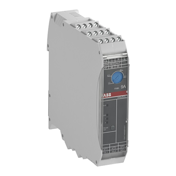
1 Product overview
Basic function
Explains how compact starters replace conventional solutions.
Applications
Lists applications for the electronic compact starter.
Hybrid technology
Explains the hybrid technology combining semiconductors and relays.
1.1 Benefits
Details advantages like space saving, safety, and ease of installation.
1.2 Product combinations
Lists recommended product combinations with power supply and pilot devices.
1.3 Explanation of terminals
Explains the function of LEDs and terminals on the starter.
2 Safety and conformity
2.1 General safety arrangements
Outlines general safety rules for installation, operation, and maintenance.
2.2 Safety arrangements in explosive areas
Details specific safety measures for potentially explosive environments.
2.3 Conformity
Lists the conformity standards and certifications the HF range complies with.
3 Functions
Direct on-line starters
Describes the functionality of direct on-line starter variants.
3.2 Reversing starters
Details the functionality and operation of reversing starter types.
3.3 Setting the nominal current
Explains the procedure for setting the nominal current using the potentiometer and LEDs.
4 Motor protection
Thermal overload protection
Explains how the starter protects motors against overload based on thermal calculation.
Phase asymmetry
Details protection against phase asymmetry and failure detection.
Phase failure
Explains detection of phase failure and corresponding motor starter response.
4.4 Signaling
Explains the function of LEDs for indicating device status, operation, and faults.
4.5 Function Test
Describes how to perform general and motor overload protection safety function tests.
5 Installation and de-installation
5.1 Installation
Covers installation requirements for DIN-rails and mounting steps.
5.2 Derating
Provides derating curves for load current based on ambient temperature and spacing.
5.3 De-installation
Details steps for de-installing the device from the DIN-rail and disposal information.
6 Commissioning
6.1 Commissioning the terminals
Explains the procedure for connecting conductors to the terminals.
6.2 Main and load terminal connection
Describes how to connect the main supply and load terminals.
6.3 Control terminals
Explains the control supply voltage and connection of control inputs for different starter types.
6.4 Reset terminals
Details reset terminal functions and signaling relay connections.
6.5 Signaling relay terminals
Explains how to connect auxiliary relays for external signals.
6.6 Short circuit protection
Single mounting
Details SCPD selection for single starter installations.
Group mounting
Explains SCPD selection for multiple starters mounted together.
6.6.1 Protection with fuses
Details fuse types for short-circuit protection in single and group mounting.
Short-circuit protection for use in UL market
Covers short-circuit protection requirements for UL applications.
7 Circuits with brakes
7.1 Motors with a 230 V AC brake
Describes wiring and setup for motors with 230V AC brakes.
7.2 Motors with a 400 V AC brake
Details wiring and setup for motors with 400V AC brakes.
8 Typical circuits for HF range types with integrated emergency stop
8.1 Prevention of cross-error circuit
Explains preventing cross-circuit failures in emergency stop installations.
8.2 Wiring standard variants
Shows wiring diagrams for standard DOL and ROL variants.
8.3 Wiring safety variants - DOLE
Illustrates various single and two-channel connections for DOLE variants to safety relays.
8.4 Wiring safety variants - ROLE
Shows various single and two-channel connections for ROLE variants to safety relays.
9 Technical data
Maximum operating altitude
Specifies the maximum altitude for operation without derating.
Mechanical vibration and shock
Details vibration resistance and shock resistance test results.
10 Dimensional drawings
Dimension drawings for all HF- types with integrated overload protection
Provides detailed physical dimensions for HF starters with overload protection.
Dimensional drawings for R- type
Shows the physical dimensions specific to the R-type starter.
11 Annex
Additional Information Resources
Points to ABB homepage and videos for further information.
Need help?
Do you have a question about the HF9-ROLE-24VDC and is the answer not in the manual?
Questions and answers