Advertisement
Quick Start Guide
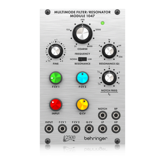
MULTIMODE FILTER /
RESONATOR MODULE 1047
Legendary 2500 Series 12dB State
Variable Filter Module for Eurorack
Controls
(1)
(2)
(3)
(5)
(6)
(8)
(9)
(10) (11) (12) (13) (14) (15)
COARSE – Use this knob to dial in the general frequency
(1)
area you want for the high-pass threshold, low-pass
threshold, band-pass center frequency and notch filter
center frequency, then go to the FINE knob to refine the
frequency setting. The frequency set by the COARSE and
FINE knobs ("fc") will be used simultaneously for every
filter in the module.
FINE – Use this knob to refine and focus the frequency set
(2)
by the COARSE FREQUENCY knob.
RESONANCE (NORM/LIM) – This sliding switch lets
(3)
you choose between normal resonance mode (NORM)
and limiting mode (LIM), which limits the height of a
filter's resonant peak. The LIM setting prevents circuit
overload when focusing a filter on a strong harmonic or
fundamental frequency, especially at high Q settings on
V 1.0
the RESONANCE (Q) knob. In other situations, the LIM
setting can result in a very low output signal, and so the
NORM setting is usually preferred.
RESONANCE (Q) – This knob controls the width/
(4)
smoothness and narrowness/sharpness of the filter
curves. At low Q settings, the filter curves are wider and
smoother, with a gentler effect on the sound (except for
the notch filter, which functions most effectively at low
Q settings). As you increase the Q setting, the filter curves
gradually become narrower and sharper, which can help
you to focus in on narrow frequency bands. At higher Q
settings, the various filters can produce resonant peaks
in the filter curves that boost some frequencies and may
require moving the RESONANCE (NORM/LIM) switch to
the LIM setting to prevent overloading the circuit (or the
INPUT attenuator knob can be turned down).
F CV 1 – This knob adjusts the strength of the control
(5)
(4)
voltage signal coming in through the F CV 1 jack.
F CV 2 – This knob adjusts the strength of the control
(6)
voltage signal coming in through the F CV 2 jack.
(7)
NOTCH FEQUENCY/fc – Use this knob to offset the notch
(7)
filter's center frequency ("fc") set by the COARSE and FINE
frequency controls. For standard notch filter behavior, the
NOTCH FREQ/fc control should be set to "1" on the scale.
(16)
This standard setting can then be tweaked by moving the
NOTCH FREQ/fc knob very slightly around "1". Also, if
higher Q values are added via the RESONANCE knob while
(17)
the notch filter is offset from fc, the higher Q values result
in a resonant peak at fc, with the notch at the point set by
the NOTCH FREQ/fc knob.
Knob Setting
Full CCW
CCW to 1/4
CW to 4
Full CW
INPUT – This knob adjusts the strength of the audio signal
(8)
coming through the INPUT jack.
Q CV – This knob adjusts the strength of the Q control
(9)
voltage signal coming in through the Q CV jack.
INPUT – Use this jack to route audio signals into the
(10)
module via cables with 3.5 mm connectors. You can also
route in a keyboard gate signal to "ring" the filter and
produce a unique percussive sound when you press a key.
Effect
Notch filter output becomes a
copy of the high-pass output
Notch frequency shifts
significantly below fc
Notch frequency shifts
significantly above fc
Notch filter output becomes a
copy of the low-pass filter output
Advertisement
Table of Contents

Related Manuals for Behringer 1047


Summarization of Contents
Multimode Filter / Resonator Module 1047 Controls
Coarse Frequency Control
Sets the general frequency area for filter thresholds and center frequencies.
Fine Frequency Control
Refines and focuses the frequency setting made by the COARSE knob.
Resonance (NORM/LIM) Switch
Selects between normal resonance mode or limiting mode to control peak height.
Resonance (Q) Control
Adjusts the width/smoothness or narrowness/sharpness of filter curves.
Frequency CV 1/2 Attenuators
Adjusts the strength of control voltage signals for filter frequency.
Notch Frequency/fc Control
Offsets the notch filter's center frequency relative to the main frequency controls.
Input/Q CV Attenuators
Adjusts the strength of the audio signal and Q control voltage signals.
Input and Output Jacks
Connections for audio input, CV inputs, and filter outputs (LP, HP, Notch, BP).
Filter Curves
Lowpass Response
Illustrates low-pass filter frequency response curves for Normal and Limit modes.
Bandpass Response
Illustrates band-pass filter frequency response curves for Normal and Limit modes.
Highpass Response
Illustrates high-pass filter frequency response curves for Normal and Limit modes.
Power Connection and Installation
Power Connection Procedure
Steps to connect the module to a standard Eurorack power supply system.
Module Installation
Instructions for mounting the module into a Eurorack case using screws.
Specifications and Notch Responses
Notch Responses
Diagrams showing notch filter behavior at different frequency offsets and Q values.
Inputs
Details on input types, impedance, max level, and CV scaling for audio and CV signals.
Outputs
Details on filter output jack types, impedance, and max output level.
Controls Specifications
Summary of control types, ranges, and functions (frequency, resonance, attenuators).
Power and Physical Specifications
Information on power supply, current draw, dimensions, rack units, and weight.
Need help?
Do you have a question about the 1047 and is the answer not in the manual?
Questions and answers