Advertisement
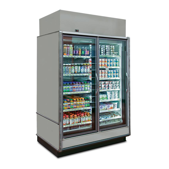
REACH-IN SELF-CONTAINED MERCHANDISER
INSTALLATION & OPERATIONS MANUAL
General Information ............................................... 6
Installation & Trim Out .....................................7-17
Connections & Piping ..........................................18
Pre-Power Checklist ............................................19
Airfl ow & Case Temperature ................................20
To ensure proper functionality and optimum performance, it is STRONGLY recommended that Hillphoenix specialty cases be installed/serviced by qualifi ed tech-
nicians who have experience working with commercial refrigerated display merchandisers and storage cabinets. For a list of Hillphoenix-authorized installation/
service contractors, please visit our website at www.hillphoenix.com.
Table of Contents
Fans & Case Cleaning .........................................21
Parts Ordering ......................................................22
Appendices ...........................................................23
JNRBHSA
JNRZHSA
P112746E
V.1 R.04
08/19
Advertisement

Related Manuals for Hillphoenix JNRZHSA


Summarization of Contents
General Information
Case Description
Identifies the specific models covered by the manual.
Store Conditions
Specifies ideal store temperature and humidity for optimal case performance.
Refrigeration System Operation
Details requirements for air-cooled condensing unit ventilation and temperatures.
Shipping and Receiving Cases
Outlines liability for shipping damage and procedures for receiving inspection.
Case Damage and Claims
Procedures for reporting and claiming damages from shipping carriers.
Lost or Missing Items
Procedure for reporting lost or missing equipment parts within 48 hours.
Service and Technical Support
Contact information for case division and systems division support.
Contacting the Factory
Information needed when contacting Hillphoenix for specific fixture support.
Case Installation: Delivery
Preparing Case for Doorway Entry
Methods to reduce case height for passage through doorways.
Lifting and Moving Cases
Procedures for lifting cases using J-bars or other manual methods.
Case Installation: Managing Components
Managing Refrigerant Lines
Instructions for flexing copper lines to clear doorways.
Electrical Box and Wiring Management
Steps for repositioning the controller box for doorway clearance.
Case Installation: Moving Through Doorways
Lifting Through Base Feet
Specific instructions and warnings for lifting cases using base feet.
Using Hydraulic Jacks
Guidance on using hydraulic jacks and designated lift points.
Case Installation: Risers and Shimming
Installing Riser Feet
Steps for attaching 3.25" riser feet to the case base.
Securing and Shimming Risers
How to secure risers and shim the case for proper alignment.
Case Installation: Floor Prep and Line-Up
Floor Preparation
Confirming dimensions, marking floor lines, and leveling.
Single Case Installation
Steps for positioning, leveling, and securing a single case.
Multi-Case Installation
Procedures for joining multiple cases together.
Case Installation: Drain and Pump Setup
PVC Drain Trap and Pump Setup
Connecting the drain trap, pump, and tubing for condensate removal.
Condensate Routing
Directing condensate to a floor drain or evaporative pan.
Case Installation: Evaporation Pan
Evaporation Pan Installation
Installing the evaporation pan and connecting tubing.
Condensate Pan Setup
Securing the pan and routing tubing for water management.
Case Installation: Trim Out - Panels
Sealing Case Joints
Applying caulk and tape to interior case-to-case joints.
Front Panel and Kickplate Installation
Aligning front panels, installing trim, and securing kickplates.
Case Installation: Condensing Unit
Connecting Refrigeration Fittings
Mating Parker quick-connect fittings and checking for leaks.
Securing Condensing Unit
Attaching the condensing unit to the case top after connections are made.
Case Installation: Air Block and Guard
Installing Air Block
Mounting the air block and securing it to the condenser coil.
Assembling Intake Guard
Nesting and fastening the intake guard to the air block.
Case Installation: Noise Dampener
Installing Noise Dampener Panels
Fitting side and top panels to reduce condensing unit noise.
Case Connections
Refrigeration Connections
Locating and connecting the condensing unit and refrigerant piping.
Plumbing Connections
Setting up the drain outlet, P-trap, and ensuring water-tight connections.
Electrical Connections
Information on junction box location, controller, and power requirements.
Airflow & Defrost
Airflow and Product Load
Guidelines for maintaining proper airflow and avoiding product overload.
Defrost and Temperature Controls
Overview of defrost types and sensor functions.
Determining Superheat
Steps to calculate and set proper superheat for the refrigeration system.
Case Cleaning & Fan Maintenance
Fan Maintenance
Steps for unplugging, removing, and replacing fan assemblies.
Cleaning Procedures
Guidelines for periodic cleaning, waste outlet checks, and light cleaning.
Appendices
Appendix A: Technical Reference Sheet
Contains detailed technical specifications for the merchandiser.
Appendix B: Seismic Brackets
Installation instructions for seismic restraint brackets.
Appendix C: Sporlan Pressure-Temperature Chart
Reference chart for refrigerant pressure-temperature relationships.
Appendix E: Electrical Wiring
Detailed electrical wiring information and diagrams.
Appendix F: Controllers and Setpoints
Information on the Carel IR33+ controller and its setpoints.
Appendix I: Case Lifting Locations
Diagrams showing safe lifting points for the case.
Appendix J: Condensing Unit Locations
Dimensional data for condensing unit placement.
Seismic Brackets Installation
Option 1: Wall Mounting
Using L-brackets to attach cases to a vertical wall.
Option 2: Base Frame Mounting
Attaching brackets to base frames for wall or floor anchoring.
Case Top Fascia Installation
Installing Coil Shroud and Fascia
Securing shroud, aligning fascia, and attaching front panel.
Electrical Box and Wiring Cover
Positioning electrical box and covering wiring with metal cover.
Electrical Wiring Diagram: Power Input
Wire Identification
Lists wire colors and terminal connections for the control system.
Electrical Wiring Diagram: Component Mapping
Component Wire Mapping
Cross-references components to wire colors and terminal numbers.
E3: Electrical Wiring Diagram
Motion Sensor Lighting Control
Wiring for optional motion sensor lighting control systems.
Condensing Unit and Fan Wiring
Connections for condensing unit, fans, and condensate pump.
E4: Electrical Wiring Diagram
Carel IR33+ Controller Wiring
Pinout and connections for the Carel IR33+ controller module.
Defrost and Heater Wiring
Wiring details for defrost heaters and other heating elements.
F1: Controllers and Setpoints
Setting Set Points
Step-by-step instructions for adjusting temperature set points.
Accessing Parameters
Procedures for accessing and modifying controller parameters.
F2: Controllers and Setpoints
Parameter List
Comprehensive table of controller parameters with definitions and ranges.
Alarm Causes and Indicators
Explains alarm codes, icons, and their corresponding causes.
F3: Controllers and Setpoints
Low Temp Set Point Adjustments
Specific set point adjustments for low-temperature applications.
Parameter Access Methods
Details on accessing parameters via 'F' (Frequent) or 'C' (Configuration) modes.
F4: Controllers and Setpoints
Beverage/Floral Set Point Adjustments
Specific set point adjustments for beverage and floral applications.
Alarm and Fan Settings
Configuration of alarm differentials and fan settings.
F5: Controllers and Setpoints
Defrost Control Settings
Configuration of defrost type, interval, and duration.
Fan Control Settings
Settings for fan operation, cycling, and response to temperature.
G1: Fascia Frame Installation
Fascia Frame Assembly
Aligning fascia panels, attaching top frame rail, and adding support brackets.
Adjustable End Fascia Panels
Fitting adjustable rear panels to the fascia frame.
G2: Fascia Frame Installation
Attaching Front and End Fascias
Securing fascia panels and top frame rail using pre-punched holes.
Front Fascia Support Brackets
Installing support brackets for the front fascia panel.
G3: Fascia Frame Installation
Junction Box and Controller Alignment
Relocating junction box and aligning display for fascia panel cutout.
G4: Fascia Frame Installation
Fastening End Caps and Signage
Securing end caps and hanging signage onto the fascia frame.
G5: Fascia Frame - Motion Sensor Install
Mounting Bracket and Sensor
Securing the mounting bracket and positioning the sensor.
Conduit and Strain Relief
Attaching flexible conduit and clamp for sensor wiring.
G6: Fascia Frame - Motion Sensor Install
Power Pack and Conduit Connection
Connecting power pack to junction box and conduit to bracket.
G7: Fascia Frame - Motion Sensor Install
Assembling and Installing Subassembly
Assembling sensor to bracket and installing into fascia.
Connecting Motion Sensor Cable
Connecting the cable from the motion sensor to the controller.
G8: Fascia Frame - Balloon Guard Installation
Balloon Guard and Sound Abatement
Installing balloon guard, side panels, and abatement around piping.
H1: End to Wall Close-Off Panels
Insulated End to Wall Panel
Installing the insulated panel and securing it with screws.
End Kick-plate to Wall Panel
Installing the end kick-plate panel for wall closure.
I1: Case Lifting Locations - 2 Door Case
2 Door Case Lifting Points
Top and front views indicating forklift access for 2-door models.
I2: Case Lifting Locations - 4 & 5 Door Cases
4 Door Case Lifting Points
Top and front views indicating forklift access for 4-door models.
5 Door Case Lifting Points
Top and front views indicating forklift access for 5-door models.
J1: Condensing Unit Locations
JNRBHSA Condensing Unit Dimensions
X and Y dimension data for JNRBHSA condensing unit placement.
JNRZHSA Condensing Unit Dimensions
X and Y dimension data for JNRZHSA condensing unit placement.
Limited Warranty
General Warranty Terms
Explains the base warranty period and eligibility for claims.
Warranty Exclusions
Lists conditions and actions that void the product warranty.
Remedy Limitation
Defines the exclusive remedy and excludes consequential damages.
Need help?
Do you have a question about the JNRZHSA and is the answer not in the manual?
Questions and answers