Advertisement
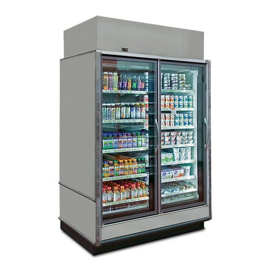
REACH-IN SELF-CONTAINED MERCHANDISER
INSTALLATION & OPERATIONS MANUAL
General Information ............................................... 6
Installation & Trim Out .....................................7-17
Connections & Piping ..........................................18
Pre-Power Checklist ............................................19
Airfl ow & Case Temperature ................................20
To ensure proper functionality and optimum performance, it is STRONGLY recommended that Hillphoenix specialty cases be installed/serviced by qualifi ed tech-
nicians who have experience working with commercial refrigerated display merchandisers and storage cabinets. For a list of Hillphoenix-authorized installation/
service contractors, please visit our website at www.hillphoenix.com.
Table of Contents
Fans & Case Cleaning .........................................21
Parts Ordering ......................................................22
Appendices ...........................................................23
JNRBHSA
JNRZHSA
P112746E
V.1 R.04
08/19
Advertisement

Subscribe to Our Youtube Channel
Related Manuals for Hillphoenix JNRBHSA


Summary of Contents for Hillphoenix JNRBHSA
-
Page 1: Table Of Contents
Airfl ow & Case Temperature ........20 To ensure proper functionality and optimum performance, it is STRONGLY recommended that Hillphoenix specialty cases be installed/serviced by qualifi ed tech- nicians who have experience working with commercial refrigerated display merchandisers and storage cabinets. For a list of Hillphoenix-authorized installation/ service contractors, please visit our website at www.hillphoenix.com. - Page 3 If a misting system or water hose is installed or used on a display case with a shelf lighting system, then Hillphoenix shall not be subject to any obligations or liabilities (whether arising out of breach of contract, warranty, tort [including negligence], strict liability or other theories of law) directly or indirectly resulting from, arising out of or related to such installation or use, including, without limitation, any personal injury, death or property damage resulting from an electrical failure, fi...
- Page 4 , the safety of our customers and employees, as well as the ongoing performance of our products, are top ® priorities. To that end, we include important warning messages in all Hillphoenix installation and operations handbooks, accompanied by an alert symbol paired with the word "DANGER", "WARNING", or "CAUTION".
- Page 5 Revision History • New Manual Format_08/14 • Manual Update_05/18 • Manual Update_01/19 • Manual Update_04/19 • Appendix F Update_05/19 • Technical Reference Sheet Update_08/19...
-
Page 6: General Information
We are always interested in your suggestions for improvements (e.g. case design, technical documents, etc.). Please feel free to contact our Marketing Services group at the number listed below. Thank you for choosing Hillphoenix, and we wish you the very best in outstanding food merchandising. -
Page 7: Installation & Trim Out
CASE INSTALLATION DELIVERY If store doorway prohibits case entry when on its delivery casters, the undercarriage may be removed to At delivery, depress ratchet to loosen strap from case top reduce overall case height under 80”. To remove under- to trailer wall. Unhook strap from wall – save strap for later carriage, lift case 1”... - Page 8 CASE INSTALLATION Once all screws are removed, (two 3/8 Hex screws located The case wiring exits into a permanent enclosure at top next to the large arrows in the photo above) the skid rails left rear of case. Flexible conduit is provided from this and caster assemblies will drop away from the case.
- Page 9 CASE INSTALLATION Once case is prepared per prior step, it can be moved thru Hydraulic pallet-rack jacks, or other manual methods may 80” door way by lifting through the base feet. *WARINING: be used, provided care is taken to protect the case, and If lifted through base feet, blades must be fully past the designated lift points are used.
- Page 10 CASE INSTALLATION Remove 3.25” riser feet from inside of the case (the ris- ers are shipped loose so the case can deliver through short doorways). Lift the case at designated areas. If using pal- let jack, avoid damaging the drain hub (centered left-right on case).
- Page 11 CASE INSTALLATION fi rst case. FLOOR PREP 4. Apply the foam tape gasket (supplied) and two beads 1. Confi rm with the general contractor that you have the of butyl or silicone sealant to the end of the fi rst case most current building dimensions, then ask for the (Fig.
- Page 12 CASE INSTALLATION TRIM OUT Drain and Pump Notes: For the best energy conservation, Hillphoenix recommends the use of fl oor drains at the store. PVC Drain Trap Pump receptacle Confi gurations exist (having ‘FD” at end of the case model name) which restrict certain selections and tailor the case for use with store fl...
- Page 13 CASE INSTALLATION DRAIN and PUMP SET-UP Place end of tube into cut-out section of cover, so that pumped condensate water is directed into the pan. 1. The shipped-loose evaporation pan gets installed at the rear left top of case. Cut away an excess section (18” to 24”...
- Page 14 CASE INSTALLATION TRIM OUT Install supplied sex bolts bolts through each frame, capturing trim, and tighten to compress sealant that was Seal the interior case-to-case joints with caulk (supplied), applied per page 11 (Fig. 4). then apply acrylic tape (supplied) over the pipechase seam (Fig.
- Page 15 CASE INSTALLATION CONDENSING UNIT The boxes of each shipped-loose, charged, condensing units are marked to identify the case to which they belong. *Import- ant! Match the condensing unit to its corresponding case. Case and condensing unit have Parket 5000-series quick-con- nect refrigeration fi...
- Page 16 CASE INSTALLATION Retrieve shipped-loose intake guard from inside case. Nest top edge into “V” retainer fl ange at top of air-block. Fasten bottom to case. Retrieve shipped-loose condensing unit air-block from inside case. Match cut outs to condensing unit and fasten by back- ing out and re-installing screws from the condenser coil.
- Page 17 CASE INSTALLATION NOISE DAMPENER [OPTIONAL] The noise damper helps to reduce the noise level of the condensing unit. Slide the right-hand panel into place using the provided slot on the back of the fascia shroud. Repeat on the left side of the condenser. If you need to, cut out enough of the foam to fi...
-
Page 18: Connections & Piping
CASE CONNECTIONS ▲ A T T E N T I O N Appendix For more detailed electrical wiring information, see E . For more detailed information on the Carel Connections are illustrated in dimensional drawing found in Appendix A. Appendix F. IR33+ controller and setpoints, see REFRIGERATION The condensing unit (Fig. -
Page 19: Pre-Power Checklist
PRE-POWER CHECKLIST Before powering-up the case, be certain that all of the steps listed below have been completed to ensure proper case functionality, safety and compliance with warranty terms. Have you thoroughly examined the case for shipping damage? (see pg. 8) Have you removed and discarded casters? (see pg. -
Page 20: Airfl Ow & Case Temperature
JNRBHSA cases utilize Off-Time defrost. The defrost termina- tion probe is housed at rear wall, behind the lower rear baffl e (Fig 9). The discharge air probe monitors the tem- perature of the discharge air and may be used as the defrost termination sensor. -
Page 21: Fans & Case Cleaning
Check waste outlet before starting the cleaning process to insure it is unclogged. Avoid introducing water Hillphoenix door cases feature electronic commutated fan faster than the case drain can carry it away. motor assemblies. The fans have a factory-set blade pitch and a pre-confi... -
Page 22: Parts Ordering
PARTS ORDERING Contact the Service Parts Department at: 1-800-283-1109 Provide the following information about the part you are ordering: • Model number and serial number* of the case for which the part is intended. • Length of the part (if applicable). •... -
Page 23: Appendices
APPENDIX A ..................Technical Reference Sheet B ......................Seismic Brackets C ................. Sporlan Pressure-Temperature Chart D ......................Case Top Fascia E ......................Electrical Wiring F ................... Controllers and Setpoints G ................Fascia Frame (Customer Specific) H ................... End To Wall Close - Off Panels I .................... - Page 24 A1: TECHNICAL REFERENCE SHEET...
- Page 25 A2: TECHNICAL REFERENCE SHEET...
- Page 26 A3: TECHNICAL REFERENCE SHEET...
- Page 27 A4: TECHNICAL REFERENCE SHEET...
- Page 28 A5: TECHNICAL REFERENCE SHEET...
- Page 29 A6: TECHNICAL REFERENCE SHEET...
- Page 30 A7: TECHNICAL REFERENCE SHEET...
- Page 31 A8: TECHNICAL REFERENCE SHEET...
- Page 32 B1: SEISMIC BRACKETS The case constraint brackets can be installed in 2 ways. Option 1 can be used on multi-deck cases and uses an “L” bracket to attach the case to a vertical wall, as shown below. Option 2 can be used on multi- deck cases or on cases that do not have a canopy.
- Page 33 B2: SEISMIC BRACKETS 5” BRACKETS...
- Page 34 C1: SPORLAN PRESSURE-TEMPERATURE CHART...
- Page 35 D1: CASE TOP FASCIA ATTN: FOR CASE TOP FASCIA WITH CUSTOMER SPECIFIC SIGNAGE SEE APPENDIX F Install the recessed coil shroud (Fig. 1), leaving about an inch of clearance on both sides of the coil. Align the ends of the front fascia to the fascia stops at each end of the case (Fig. 2). Attach the front fascia to the recessed coil shroud baffl...
- Page 36 E1: ELECTRICAL WIRING DIAGRAM Note: After case is fully wired and energized the factory-programmed CAREL will take control of the case. On case models using Real Time Clock functionality (e.g. Low Temperature JNRZHSA cases) it is recommended to update the *hour* and *minute* parameters of the CAREL Real Time Clock to the local time at the store.
- Page 37 E2: ELECTRICAL WIRING DIAGRAM WIRE IDENTIFICATION WIRE IDENTIFICATION BLACK WHITE BLUE YELLOW PURPLE ORANGE GREEN DEFROST HEATERS (1-PHASE) DEFROST HEATERS (3-PHASE) ANTI-CONDENSATE HEATERS AISLE WARMER DRAIN HEATER PRIMARY FANS SECONDARY FANS AMBIENT FANS LIGHTS 60,62 BELL 19,20 TEMPERATURE CONTROL DEFROST TERMINATION CONTROL DEFROST SAFETY CUT-OUT CONTROL LIQUID LINE SOLENOID SUCTION LINE SOLENOID...
- Page 38 E3: ELECTRICAL WIRING DIAGRAM...
- Page 39 E4: ELECTRICAL WIRING DIAGRAM...
- Page 40 F1: CONTROLLERS AND SETPOINTS...
- Page 41 F2: CONTROLLERS AND SETPOINTS...
- Page 42 F3: CONTROLLERS AND SETPOINTS...
- Page 43 F4: CONTROLLERS AND SETPOINTS...
- Page 44 F5: CONTROLLERS AND SETPOINTS...
- Page 45 F6: CONTROLLERS AND SETPOINTS...
- Page 46 G1: FASCIA FRAME...
- Page 47 G2: FASCIA FRAME...
- Page 48 G3: FASCIA FRAME...
- Page 49 G4: FASCIA FRAME...
- Page 50 G5: FASCIA FRAME (OPTIONAL MOTION SENSOR INSTALLATION)
- Page 51 G6: FASCIA FRAME (OPTIONAL MOTION SENSOR INSTALLATION)
- Page 52 G7: FASCIA FRAME (OPTIONAL MOTION SENSOR INSTALLATION) 1. Use fasteners to assemble the motion sensor to the bracket, and then install the subassembly into the case fascia. 2. Install the motion sensor/bracket subassembly into the fascia. 3. Connect cable to motion sensor and to controller.
- Page 53 G8: FASCIA FRAME (JNRZHSA-5 BALLOON GUARD INSTALLATION)
- Page 54 H1: END TO WALL CLOSE-OFF PANELS If ordered, the 4 shipped-loose items, trims from the ends of the case to the wall behind. Close-off panel: Insulated End to Wall Right Hand shown. Nominal 77” Height. Hemmed top rests on top of insulated end panel. Slide back to close any gaps to the wall behind. Fasten with #8 screws at holes provided.
- Page 55 I1: CASE LIFTING LOCATIONS Base Frame Lifting Locations for Forklift – JNRBHSA/JNRZHSA...
- Page 56 I2: CASE LIFTING LOCATIONS Base Frame Lifting Locations for Forklift – JNRBHSA/JNRZHSA...
- Page 57 J1: CONDENSING UNIT LOCATIONS...
- Page 58 1925 Ruffin Mill Rd, Colonial Heights, VA 23834 Due to our commitment to continuous improvement, all specifications are subject to change without notice. Hillphoenix is a Sustaining Member of the American Society of Quality. Visit our website at www.hillphoenix.com BDM0818...
- Page 59 Hill PHOENIX, Inc. Hereinafter Referred To As Manufacturer LIMITED WARRANTY GENERAL WARRANTY Manufacturer’s products are warranted to be free from defects in materials and workmanship under normal use and maintenance for fourteen months from date of shipment from manufacturer (the “Base Warranty Period”). In the event of a qualifying warranty claim, a new or rebuilt part to replace any defective part will be provided without charge.
Need help?
Do you have a question about the JNRBHSA and is the answer not in the manual?
Questions and answers