Table of Contents
Advertisement
Advertisement
Table of Contents

Related Manuals for Siemens 6DL1132-6HD50-0PK0


Summarization of Contents
Security Information
Validity of the Documentation
Details the validity period and scope of this device manual, including its relation to system manuals.
Appendices
Provides information relevant for using the ET 200SP HA outside the PCS 7 environment.
Conventions
Explains symbols and notes used in the manual, particularly 'Note' for important information.
Product Overview
Properties of the I/O Module
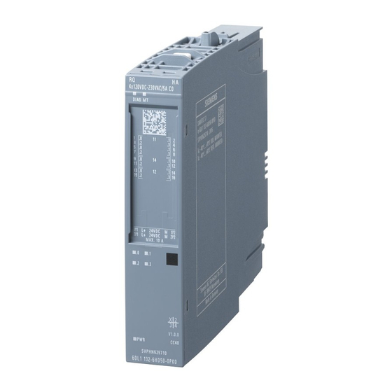
Details the technical properties and functions of the RQ 4x120VDC-230VAC/5A CO HA I/O module.
Output Disable Switch
Explains how to use the output disable switch for safe module removal during runtime.
Accessories
Lists accessories that must be ordered separately for the I/O module.
Wiring
Pin Assignment of the I/O Module
Provides the terminal pin assignment for the RQ 4x120VDC-230VAC/5A CO HA I/O module.
Schematic Circuit Diagram
Illustrates the block diagram and internal connections of the RQ 4x120VDC-230VAC/5A CO HA.
Parameters
Module Parameters
Explains how to configure the I/O module using parameters in PCS 7.
Module and Channel Parameters
Details the setting options, default values, and re-assignment capabilities for module and channel parameters.
Explanation of Module/Channel Parameters
Provides a detailed explanation of parameters like Diagnostics, Channel activated, Reaction to CPU STOP, and Potential group.
Displays and Interrupts
Status and Error Displays (LEDs)
Describes the LED displays (DIAG, MT, Channel status, PWR) on the I/O module and their meanings.
Interrupts and Messages
Details diagnostics interrupts and maintenance messages generated by the I/O module.
Technical Specifications
General Product Information
Covers article number, product type designation, firmware version, engineering, and redundancy capabilities.
Electrical and Performance Specifications
Details supply voltage, input current, power loss, address space, digital outputs, switching frequency, and total output current.
Relay Output and Switching Capacity
Details relay output specifications, switching capacity for various loads, and maximum cable length.
Diagnostics and Safety Features
Explains diagnostic functions, alarms, messages, indication LEDs, and potential separation features.
Isolation and Environmental Data
Covers electrical isolation, operating ambient conditions, module dimensions, and weight.
Drivers, Parameters, Diagnostics Messages and Address Space
Concept of Driver and Diagnostics Blocks
Explains the concept of driver and diagnostics blocks for process control systems like PCS 7.
Parameter Assignment in User Program
Describes how to reconfigure module channels in RUN and the output parameter STATUS for error handling.
Structure of Module/Channel Parameters
Details the structure of data record 128, including header and channel parameter bytes.
Diagnostics Messages and Maintenance Events
Lists diagnostic messages, their error codes, meanings, and corrective measures, plus maintenance events.
Address Space Mapping
Shows the mapping of input and output address space for the module and explains value status interpretation.
Need help?
Do you have a question about the 6DL1132-6HD50-0PK0 and is the answer not in the manual?
Questions and answers