
Related Manuals for LUDLUM 375-30


Summarization of Contents
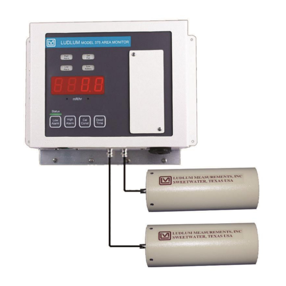
Section 1: Introduction to Model 375 Area Monitors
Model 375 Systems Overview
Details the various Model 375 systems and their detector configurations.
Model 44-137 Detector Specifications
Describes the physical and performance characteristics of the Model 44-137 detector.
Model 44-99 Detector Specifications
Details the specifications for the Model 44-99 scintillation detectors.
Section 2: Getting Started with Model 375
Powering Up the Model 375
Instructions for initial power-up and basic operation of the instrument.
Understanding Radiation Units
Explains the various radiation units of measure supported by the Model 375.
Checking Instrument Parameters
How to check and view low alarm, high alarm, calibration constant, and dead time.
Setting Alarm Points
Procedure for setting low and high alarm points for the instrument.
Performing an Operational Check
Guidance on how to perform an operational check using a radiation check source.
Section 3: Model 375 Specifications
Display and Unit Information
Details the four-digit LED display, range, and supported units of measure.
Instrument Response and Indicators
Describes response time, status lights, and indicators for alarms and failures.
Connector and Communication Interfaces
Details the instrument's connectors, Ethernet, RS-232, and remote capabilities.
Operational Controls and Power
Covers calibration controls, HV, dead time, overload, power supply, and battery life.
Section 4: Operator Controls and Setup
Calibration Potentiometer Controls
Details the function of the Analog, HV, Discriminator, Battery Charge, and Overload potentiometers.
Dipswitch Configuration Settings
Explains the function of the four-pole dipswitch for various options.
RS-232 Data Output Format
Describes the format and content of data sent via the RS-232 port.
9-Pin Remote Data Connector Pinouts
Lists the pin assignments for the 9-pin connector for data and voltage input.
9-Pin Relays Connector Pinouts
Details the pin assignments for the 9-pin connector for fail-safe relays.
Model 375-20 Detector Setup
Typical response and set points for the Model 375-20 with Model 44-137 detectors.
Models 375-30, 375-32, 375-34 Detector Setup
Typical response and set points for Models 375-30, 375-32, 375-34 with Model 44-99 detectors.
Section 5: Common Options and Modifications
Relay Options Overview
Details internal circuit-board-mounted relays and optional Form C relay.
External Mains Alarm Relay Out Option
Describes the option for external mains voltage alarm relay output using a 3-pin connector.
Ethernet Interface Option
Details the 10-BaseT Ethernet interface for network reporting via Ludlum software.
Time and Date Stamp Option
Explains how the instrument prints readings, date, time during alarms or failures.
Printer DIP Switch Settings
Configuration settings for the Citizen Dot Matrix Printer Model CBM-910.
Sigma Alarm Modification Option
Describes a sigma-based alarm point feature and its configuration.
4 to 20 mA Isolated Output Driver Option
Details the modification kit for providing an isolated 4 to 20 mA output.
Section 6: Safety Considerations
Environmental Conditions for Operation
Specifies the required temperature, humidity, and mains voltage conditions.
Cleaning and Maintenance Precautions
Instructions on how to safely clean the instrument externally.
Understanding Warning Markings and Symbols
Explains various caution and warning symbols used on the instrument.
Main Fuse Replacement Procedure
Instructions for safely replacing the main fuse to prevent fire risk.
Detector Connector Electrical Safety
Warning regarding potential electrical shock hazard from detector connectors.
General Electrical Safety Precautions
Important instructions to avoid hazardous situations and potential injury.
Section 7: Calibration Procedures
Calibrating High Voltage
Procedure for setting and checking the high voltage required for detector operation.
Adjusting Calibration Parameters
How to set low alarm, high alarm, calibration constant, and dead time.
Analog Output Calibration
Description of the five-decade logarithmic analog output and its calibration.
Discriminator and Battery Charge Settings
Details on setting the pulse threshold and backup battery trickle-charge voltage.
Section 8: Recycling Information
Recyclable Materials Identification
Lists types of recyclable materials found in Ludlum products.
Section 9: Receiving and Installation
Unpacking and Checking Contents
Instructions for unpacking, verifying contents, and handling shipments.
Installation Guide for Models 375-20 & 375-30
General guidance for installing these specific wall-mount area monitor models.
Installation Guide for Models 375-32 & 375-34
General guidance for installing these specific wall-mount area monitor models.
Section 10: Parts List
Model 375 Assemblies and Detectors
Lists completely assembled units and associated detectors for various models.
Main Board and Component Parts
Lists parts for the main circuit board, crystals, and capacitors.
Transistors and Diodes
Lists various transistors, integrated circuits, and diodes used in the instrument.
Switches, Potentiometers, and Resistors
Lists various switches, potentiometers, and resistors used in the instrument.
Connectors and Other Components
Lists connectors, inductors, relays, transformers, and other miscellaneous parts.
Section 11: Technical Drawings
Model 375 Instrument Drawings
Lists drawings for the main circuit board and wiring diagram.
Model 375-20 System Drawings
Drawings related to the Model 375-20 aerial view, detector, scale, and ISO view.
Model 375-20 & 375-30 System Drawings
Drawings for the connector plate assembly for these models.
Model 375-30, 375-32 & 375-34 System Drawings
Drawings for overall views of the Model 44-99 detectors used in these systems.
Model 375-30 System Installation Drawings
Drawings for typical installation and enclosure of the Model 375-30.
Model 375-32 & 375-34 System Drawings
Drawings for assembly, mounting, and final assembly of these systems.
Need help?
Do you have a question about the 375-30 and is the answer not in the manual?
Questions and answers