
Subscribe to Our Youtube Channel
Related Manuals for LUDLUM 375-20

Summary of Contents for LUDLUM 375-20
- Page 1 LUDLUM MODELS 375-20, 375-30, 375-32 AND 375-34 DIGITAL WALL-MOUNT AREA MONITORS September 2020 Serial Number 278020 and Succeeding Serial Numbers...
- Page 2 LUDLUM MODELS 375-20, 375-30, 375-32 AND 375-34 DIGITAL WALL-MOUNT AREA MONITORS September 2020 Serial Number 278020 and Succeeding Serial Numbers...
- Page 4 RETURN OF GOODS TO MANUFACTURER If equipment needs to be returned to Ludlum Measurements, Inc. for repair or calibration, please send to the address below. All shipments should include documentation containing return shipping address, customer name, telephone number, description of service requested, and all other necessary information.
-
Page 6: Table Of Contents
Printer DIP Switch Settings Sigma Alarm Modification Option 4 to 20 mA Isolated Output Driver Option Safety Considerations Environmental Conditions for Normal Use Cleaning Instructions and Precautions Warning Markings and Symbols Replacement of Main Fuse Detector Connector Ludlum Measurements, Inc. September 2020... - Page 7 MODELS 375-20, 375-30, 375-32 & 375-34 Electrical Safety Precautions Calibration High Voltage Calibration Parameters Analog Output Discriminator Battery Charge Recycling Receiving and Installation Unpacking and Repacking Installation Models 375-20 & 375-30 Models 375-32 & 375-34 Parts List Model 375-20 Digital Wall-Mount Area Monitor...
-
Page 8: Introduction
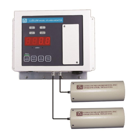
MODELS 375-20, 375-30, 375-32 & 375-34 Section 1 Section Introduction he Model 375 Digital Wall-Mount Area Monitor is designed to monitor for nuclear radiation. Featuring a wall-mount chassis, the Model 375 has a four-digit LED display that is readable from 9 m (30 ft) away. - Page 9 The Model 44-137 contains lead shields around the crystal, which allow specific coverage areas for radiation detection. These detectors are included with the Ludlum Model 375-20 Waste Monitor. Model 44-137: : two each 5.1 x 5.1 cm ( 2 x 2 in.) diameter thick shielded NaI(Tl)
- Page 10 The Model 44-99 contains lead shields around the crystal, which allow specific coverage areas for radiation detection. These detectors are included with the Ludlum Model 375-30 Waste Monitor. Model 44-99: : 2 ea. 7.6 cm (3 in.) diameter x 2.5 cm (1 in.) thick shielded NaI(Tl)
-
Page 11: Getting Started
MODELS 375-20, 375-30, 375-32 & 375-34 Section 2 Section Getting Started he Model 375 Digital Wall-Mount Area Monitor is designed for ease of use. This section of the manual is designed to help the first- time user get started. Initial power-up and basic features of the Model 375 will be discussed in this section. -
Page 12: Radiation Units
MODELS 375-20, 375-30, 375-32 & 375-34 Section 2 When the instrument has finished measuring background, it will display the current radiation reading and begin checking for an alarm condition. Radiation Units The Model 375 may be calibrated for almost any desired radiation units of measure. -
Page 13: Operational Check
The operational check is an important assurance that the radiation detector and electronics are working correctly. Note: Ludlum Measurements suggests that an operational check be performed on a regular basis. Local procedures may supersede this suggestion. For an operational check, it is necessary to use a radiation check source (not included, but available). - Page 14 MODELS 375-20, 375-30, 375-32 & 375-34 Section 2 1. Taking the source in hand, place it so that it is located on or near the center (same location each time) of one of the detectors. Hold it there for approximately five seconds or until the reading stabilizes.
-
Page 15: Specifications
MODELS 375-20, 375-30, 375-32 & 375-34 Section 3 Section Specifications : four-digit LED display with 2 cm (0.8 inch) character height Display : 000.0-9999 Display Range Display Units : can be made to display in µR/hr, mR/hr, R/hr, µSv/h, mSv/h, Sv/h, µrem/hr, mrem/hr, rem/hr, cpm, cps, and others... - Page 16 MODELS 375-20, 375-30, 375-32 & 375-34 Section 3 : dependent upon the system Connector 10 Base-T connection for use with Ludlum software Ethernet (optional): : accessible from the front of the instrument Calibration Controls (protective cover provided) : adjustable from 450 to 2500 V...
-
Page 17: Operator Controls And Setup
DISC pulses from the detector. The pad allows direct measurement of threshold voltage. Utilize a Ludlum Model 500 pulser or equivalent to inject pulses of the desired threshold size. The pulse height threshold is adjustable from 2.0 mVdc to 100 mVdc. -
Page 18: Dipswitch (Under Calibration Cover)
MODELS 375-20, 375-30, 375-32 & 375-34 Section 4 Dipswitch (under calibration cover) When the calibration cover is removed, a four-pole dipswitch is accessible that can activate or deactivate options. These four options are CAL MODE , and LATCH ALARM RANGE... -
Page 19: Rs-232 Output
MODELS 375-20, 375-30, 375-32 & 375-34 Section 4 RS-232 Output With the dipswitch in the left position, the Model 375 dumps RS- CAL MODE 232 data onto pin 4 of the 9-pin connector every two seconds. BYTE1 BYTE2 BYTE3 BYTE4... -
Page 20: 9-Pin Relays Connector
AlarmNC Detector Setups Model 375-20 Typical response and set points for the Model 375-20 with Model 44-137 Scintillation Detectors are as follows: Operating Voltage: 600-1200 Vdc, determined by comparing plateaus Threshold: 10 mVdc (using a 0.99 m {39 in.} cable) Calibration Constant: 1600 cpm/µR/hr... - Page 21 MODELS 375-20, 375-30, 375-32 & 375-34 Section 4 MODELS 375-30, 375-32 & 375-34 Typical response and set points for Models 375-30, 375-32, and 375-34 with Model 44-99 Scintillation Detectors are as follows: Operating Voltage: 600-1200 Vdc, determined by comparing plateaus Threshold: 10 mVdc (using a 0.99 m {39 in.} cable)
-
Page 22: Common Options And Modifications
MODELS 375-20, 375-30, 375-32 & 375-34 Section 5 Section Common Options and Modifications Relay Options Internal Circuit-Board-Mounted Relays A 9-pin connector with male pins provides connection to three fail-safe form C relays, activiated by the LOW ALARM (alert), HIGH ALARM, and instrument FAIL. - Page 23 MODELS 375-20, 375-30, 375-32 & 375-34 Section 5 External Mains (120 or 240 VAC) Alarm Relay Out (using 3 pin connector) PN4558-038 Allows the use of the 9-pin D female connector for RS-232 or remote use and does not interfere with the internal form C relays.
- Page 24 MODELS 375-20, 375-30, 375-32 & 375-34 Section 5 Figure 2. Mains Relay Box Front Panel. See below for description of noted parts in drawing above. A – conduit connector to the box if necessary. B – AC receptacle (removed if using conduit).
- Page 25 B – relay output. “H” = hot and “N” = neutral. For 220 Vac, H = L1 and N = L2. C – optional conduit connector input. D – optional relay output for conduit. Strobe lights and/or horns are also available through Ludlum Measurements. Ludlum Measurements, Inc. Page 5-4...
-
Page 26: Ethernet Interface Option
MODELS 375-20, 375-30, 375-32 & 375-34 Section 5 Ethernet Interface Option A 10-BaseT Ethernet interface may be added internally for network reporting, using Ludlum software: 4558-098 LMI “Ethernet” Hardware Interface 4558-105 LMI “Webpage” Hardware Interface Either the Ethernet software (1370-055) or the Webpage software (1370-077) must be purchased separately (site-licensed). -
Page 27: Printer Dip Switch Settings
MODELS 375-20, 375-30, 375-32 & 375-34 Section 5 The year can be adjusted from 0000 to 9999 using the UP and DOWN arrow buttons. Check the hours and minutes (HHMM) by pressing the LOW ALARM buttons simultaneously. The hours and minutes will be displayed DEAD TIME as long as those buttons are pressed. -
Page 28: Sigma Alarm Modification Option
MODELS 375-20, 375-30, 375-32 & 375-34 Section 5 Sigma Alarm Modification Option With this option, special firmware allows the Model 375 to have a sigma-based alarm point in addition to a regular fixed alarm point. This sigma-based alarm point allows the user to have a floating alarm point that will stay at “x” sigma above the radiation background. -
Page 29: To 20 Ma Isolated Output Driver Option
MODELS 375-20, 375-30, 375-32 & 375-34 Section 5 4 to 20 mA Isolated Output Driver Option 4 – 20 mA Driver (Isolated) Modification Kit Part Number 4558-104 This circuit may be added to the Model 375 analog output, providing an isolated 4 to 20 mA output capability. - Page 30 MODELS 375-20, 375-30, 375-32 & 375-34 Section 5 SPECIFICATIONS : 7.5 Vdc at 100 mA, minimum V = 5.5 V and Power Required maximum V = 15 V : 250 ohm Terminating Resistor Model 375 Recorder Output Connections (9-pin D-sub connector) Pin 5 is “SIG”, current output (was voltage output)
-
Page 31: Safety Considerations
MODELS 375-20, 375-30, 375-32 & 375-34 Section 6 Section Safety Considerations Environmental Conditions for Normal Use Indoor use only (instrument); indoor or outdoor use (detectors) No maximum altitude Temperature range of -20 to 50 °C (-4 to 122 °F); may be certified for operation from -40 to 65 °C (-40 to 150 °F) -
Page 32: Warning Markings And Symbols
The operator or responsible body is cautioned that the protection provided by the equipment may be impaired if the equipment is used in a manner not specified by Ludlum Measurements, Inc. This series of Model 375 instruments is marked with the following symbols: CAUTION, RISK OF ELECTRIC SHOCK (per ISO 3864, No. -
Page 33: Replacement Of Main Fuse
MODELS 375-20, 375-30, 375-32 & 375-34 Section 6 The “crossed-out wheelie bin” symbol notifies the consumer that the product is not to be mixed with unsorted municipal waste when discarding; each material must be separated. The symbol is placed near the AC receptacle. - Page 34 MODELS 375-20, 375-30, 375-32 & 375-34 Section 6 Do not cut, kink, otherwise damage nor modify the power supply cord. In addition, avoid using the power cord in close proximity to heaters, and never place heavy objects – including the unit itself – on the power cord, as doing so may result in fire or electric shock.
-
Page 35: Calibration
"low" radiation field. A "low" radiation field in this case is defined as a field where dead time losses do not exceed 5%. The calibration constant is usually given for a certain detector. A Ludlum Model 44-137 detector has a calibration constant of 1000 cpm (1 kcpm). A Ludlum Model 44-99 detector has a calibration constant of approximately 2400 cpm/µR/hr. -
Page 36: Analog Output
MODELS 375-20, 375-30, 375-32 & 375-34 Section 7 during the detector's dead time. Scintillation detectors generally have short dead times of 1-10 microseconds. Note: Once parameters are set, it is important to remember to switch the switch back to the left. This action CAL MODE protects the parameters from inadvertent changes. -
Page 37: Recycling
To this end, Ludlum Measurements, Inc. strives to supply the consumer of its goods with information regarding reuse and recycling of the many different types of materials used in its products. With many different agencies –... -
Page 38: Receiving And Installation
The Model 375 serial number is located on the lower left corner of the front panel. Most Ludlum Measurements, Inc. detectors have a label on the base or body of the detector for model and serial number identification. -
Page 39: Installation
Section 9 Installation MODELS 375-20 & 375-30 The following is intended to be a general guide for installing the Ludlum Model 375-20 or 375-30 Wall-Mount Area Monitor. Exact installation details depend on the customer’s specific location and use. : The placement of the detector will depend on the relative... -
Page 40: Models 375-32 & 375-34
: Remote alarm monitors such as the OPTIONAL REMOTE ALARMS Model 271 or 272 may be operated by the Model 375-20 and 375-30. MODELS 375-32 & 375-34 The following is intended to be a general guide for installing the Ludlum Model 375-32 or 375-34 Wall-Mount Area Monitor. - Page 41 MODELS 375-20, 375-30, 375-32 & 375-34 Section 9 INSTRUMENT (COUNTER) : Connect the instrument to mains power. The Model 375 instrument is designed for indoor use only and must be protected from adverse weather conditions. Note: Model 375 units will normally be wired internally for 120 Vac.
-
Page 42: Parts List
MODELS 375-20, 375-30, 375-32 & 375-34 Section 10 Section Parts List Reference Description Part Number UNIT Completely Assembled Model 375-20 Digital Model 375-20 48-3245 Wall-Mount Area Monitor 2 ea. Model 44-137 Detector 47-3113 UNIT Completely Assembled Model 375-30 Digital Model 375-30... - Page 43 MODELS 375-20, 375-30, 375-32 & 375-34 Section 10 Reference Description Part Number C9-C11 100µF, 16V 04-5794 C12-C21 0.1µF, 500V 04-5696 C22-C23 0.01µF, 3kV 04-5762 C24-C33 0.1µF, 500V 04-5696 100pF, 100V 04-5743 10µF, 25V 04-5728 100pF, 100V 04-5743 100µF, 16V 04-5794 C39-C40 10µF, 25V...
- Page 44 MODELS 375-20, 375-30, 375-32 & 375-34 Section 10 Reference Description Part Number VOLTAGE VR341 LT1129CQ-5 06-6372 REGULATOR INTEGRATED MAX985EUK+T 06-6459 CIRCUITS LT1304CS8 06-6394 ICL7660SCBAZ 06-6437 TCM810LVNB713 06-6424 SA08-11EWA 07-6389 KB-2785YW 07-6371 KB-2685EW 07-6400 U111 ICM7218CIQI-LFT 06-6311 U131 SA08-11EWA 07-6389 U201...
- Page 45 MODELS 375-20, 375-30, 375-32 & 375-34 Section 10 Reference Description Part Number CR38 US1M-E3 07-6530 CR341-CR342 CMSH1-40M 07-6411 DS11 KB-2550SGD 07-6370 SWITCHES S001 ALERT POINT 08-6728 S101 ALARM POINT 08-6728 S201 CALIBRATION CONSTANT 08-6728 S301 DEADTIME CORRECTION 08-6728 S501 DOWN...
- Page 46 MODELS 375-20, 375-30, 375-32 & 375-34 Section 10 Reference Description Part Number R142 60.4ohm, 1%, 250mW 12-7962 R151-R152 100K, 1%, 250mW 12-7834 R201 24.3K, 1%, 250mW 12-7867 R241 2.21K, 1%, 250mW 12-7835 R251 10K, 1%, 250mW 12-7839 R252 24.3K, 1%, 250mW...
- Page 47 MODELS 375-20, 375-30, 375-32 & 375-34 Section 10 Reference Description Part Number 640457-2 MTAX2RA ALARM OUT 13-8147 INDUCTORS 1Kohm 21-9008 L3-L4 2700ohm 21-9009 2700ohm 21-9009 1Kohm 21-9008 L411 220µHY 21-9678 RELAY RL1-RL3 G6K-2FY DC5 22-9332 TRANSFORMER 32377R 21-9925 MISCELLANEOUS SOCKET 44P PLCC...
-
Page 48: Wiring Diagram, Drawing 558 X 136
Model 375-20 Scale, Drawing 385 × 576C Model 375-20 ISO VIEW, Drawing 385 × 576D Model 44-137 ASSY., Drawing 385 × 386 Model 44-137 WEATHER ENCLOS. Assy., Drawing 385 × 577 Model 375-20, 375-30 Connector Plate Assy., Drawing 396 x 588B Model 375-20 and 375-30 Systems Model 44-99 OVERALL VIEW, Drawing 385 ×... - Page 49 MODELS 375-20, 375-30, 375-32 & 375-34 Section 11 Model 375-30/3530 Detector Mounting, Drawing 385 × 120 Model 375-30 Installation, Drawing 396 x 170A and 170B Model 375-32; 375-34, Drawing 385 × 60 Model 375-32 & 375-34 Systems Model 375-32; 375-34 ASSY., Drawing 385 × 60A Detector Bracket Mount Assy., Drawing 385 ×...
Need help?
Do you have a question about the 375-20 and is the answer not in the manual?
Questions and answers