
Related Manuals for Husqvarna K 3000-Cut-n-Break


Summarization of Contents
LITERATURE
Workshop Manual Overview
Provides a general overview of the workshop manual's scope and purpose for K3000 models.
Machine Disposition
Explains how the manual addresses common motor units and machine-specific parts for K3000 variants.
Manual Arrangement and Text
Details the manual's structure with two text columns for mechanics of varying experience levels.
Spares Information
Describes the availability of spare parts folders for K3000 Electric, Wet, and Cut-n-Break models.
COMPONENTS – NAVIGATION
K3000 Electric, Wet Components
Identifies and illustrates the main components of the K3000 Electric and Wet models.
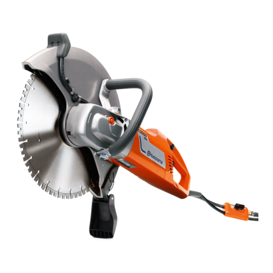
K3000 Cut-n-Break Components
Identifies and illustrates the main components specific to the K3000 Cut-n-Break model.
BASIC STRUCTURE
K3000 Electric Basic Design
Describes the K3000 Electric model's design, suitable for 300/350mm blades for dry cutting.
K3000 Wet Basic Design
Details the K3000 Wet model, identical to Electric but with a wet cutting attachment.
K3000 Motor Unit
Explains the common motor unit for all K3000 models, available in 230V and 120V.
K3000 Cut-n-Break Structure
Describes the K3000 Cut-n-Break, featuring double blades and blade water coolant.
CARBON BRUSHES
Replacing Carbon Brushes
Step-by-step instructions for replacing worn carbon brushes on K3000 models.
Checking Worn Carbon Brushes
Guidance on how to inspect carbon brushes for wear and potential damage.
Sparking Prevention
Important advice on avoiding sparking near the collector to prevent damage.
CARBON BRUSH HOLDER
Replacing Carbon Brush Holder
Overview of the procedure to replace carbon brush holders, involving handle removal.
Removing Handle Halves
Detailed steps for removing the right and left handle halves to access components.
Removing Brush Holders
Instructions on how to detach the carbon brush holders from the motor housing.
WIRING DIAGRAM, CABLING – 230 V
230V Assembly Diagram
Illustrates the colors and positions of connection cables for electrical connections.
230V Components and Cables
Details the components and cables involved in the 230V wiring, including their positions.
WIRING DIAGRAM, CABLING – 120 V
120V Assembly Diagram
Illustrates the colors and positions of connection cables for 120V electrical connections.
120V Components and Cables
Details the components and cables for the 120V wiring, including their positions.
TESTING – ELECTRICAL COMPONENTS
Work Procedure
Outlines the general procedure for checking electrical functions using a multimeter.
Circuit Board Functions
Explains the functions of the circuit board, including soft start and overload protection.
Earth Fault Breaker Function
Describes the principle of operation for the earth fault breaker.
Function Test Procedure
Details how to perform a function test on the earth fault breaker.
ELECTRICAL CABLES – CONTACTS
Mains Cable Testing
Instructions for testing the mains cable, including separating earth fault breaker ends.
Measuring Instruments and Methods
Details the multimeter usage for testing circuits and connections.
Cable Tests
Procedures for testing continuity of various cable connections like mains to earth fault breaker.
Circuit Breaker Testing
Method for testing the circuit breaker's contact points.
ROTOR
Functional Test Preparation
Steps required before performing functional tests on the rotor, including access.
Measuring Cables and Inductance
Guidance on using measuring cables and the principle of inductance measurement for rotors.
Rotor Testing and Values
Instructions for testing the rotor's inductance and expected measured values.
Rotor Assembly and Torque
Details on rotor assembly, including tightening torque for the nut.
ROTOR – REPLACEMENT
Preparations for Rotor Replacement
Initial steps for replacing the rotor on K3000 Electric, Wet, and Cut-n-Break models.
Handle Removal
Instructions for removing the right and left handle halves to access the rotor.
Dividing Gear and Motor Housing
Steps for separating the gear housing from the motor unit to access the rotor.
STATOR – 230 V
Stator Functional Tests
Methods for identifying fractures or short circuits in the stator winding.
Resistance and Inductance Measurement
Procedures for measuring stator winding resistance and inductance.
Preparations and Measured Values
Steps for stator testing and typical measured values for 230V stators.
STATOR – 120 V
Stator Functional Tests
Methods for identifying stator winding fractures or short circuits.
Resistance and Inductance Measurement
Procedures for measuring stator winding resistance and inductance.
Preparations and Measured Values
Steps for stator testing and typical measured values for 120V stators.
STATOR – REPLACEMENT
Removing Handles and Rotor
Steps for removing handles and rotor to gain access for stator replacement.
Removing the Stator
Instructions on how to detach and remove the stator from the motor housing.
GEAR HOUSING – Electric, Wet
Dismantling and Cover Removal
Procedure for accessing and removing the gear housing cover and drive pinion.
Drive Pinion and Nut Procedures
Guidance on removing the drive pinion, noting the left-threaded nut.
Gear Housing and Bearing Removal
Steps for removing the gear housing, circlip, and bearings.
Bearing Fitting and Crown Gear Installation
Procedures for fitting gear housing bearings and installing the crown gear.
Lubrication and Final Assembly
Instructions for lubricating the gear housing and completing the assembly.
GEAR HOUSING – Cut-n-Break
Dismantling and Cover Removal
Procedure for dismantling the gear housing and removing its cover.
Drive Pinion and Nut Procedures
Steps for removing the drive pinion, noting the left-threaded nut.
Gear Housing and Bearing Removal
Instructions for removing the gear housing, circlip, and bearings.
Bearing Fitting and Lubrication
Procedures for fitting bearings and lubricating the gear housing.
CUTTING UNIT – Electric, Wet
Blade Guard and Bushing Removal
Steps for removing the blade guard and center bushing from the cutting unit.
Washer Removal and Inspection
Procedure for removing and inspecting washers and seals in the cutting unit.
Blade Guard and Seal Ring Fitting
Instructions for fitting the blade guard and seal ring.
Centre Bushing Installation
Detailed steps for correctly installing the center bushing.
CUTTING UNIT – Cut-n-Break
Belt and Blade Procedures
Instructions for belt tensioning, blade replacement, and removal.
Belt, Wheel and Guard Maintenance
Procedures for belt replacement, wheel removal, and fitting guards.
Bearing and Holder Servicing
Steps for bearing replacement and removal/fitting of the bearing holder.
Cutting Unit Separation
Instructions for removing the complete cutting unit and separating its components.
WET SYSTEM
Water Coupling and Filter Maintenance
Details on the water coupling with flow control and filter replacement.
Spray Nozzle Procedures
Instructions for replacing and fitting spray nozzles for the K3000 Wet model.
Cut-n-Break Wet System
Description of the wet system construction for the K3000 Cut-n-Break.
TOOLS
Husqvarna Acquired Tools
Lists tools available for purchase from Husqvarna for servicing the K3000.
Non-Husqvarna Servicing Tools
Lists special tools needed for K3000 servicing that are not sold by Husqvarna.
Need help?
Do you have a question about the K 3000-Cut-n-Break and is the answer not in the manual?
Questions and answers